| English
10
NOTE
According to the applicable product liability laws,
the manufacturer of the device does not assume lia
-
bility for damages to the product or damages caused
by the product that occurs due to:
f
Improper handling no complied with the operat
-
ing instructions.
f
Repairs by third parties and not by authorized ser
-
vice technicians.
f
Installation of non-original spare parts.
f
Non-intended use.
f
Electrical system breakdown due to power of the
machine in a manner not compliant with the elec
-
tric and VDE regulations.
TECHNICAL DATA
Article Number
46 424
Model
PWH 140 PLUS
Rated voltage
V
230/240
Rated frequency
Hz
50
Phase
Ph
1
Maximum operating pres
-
sure
bar
140
Maximum flow rate
l/h
450
Thermal capacity
kW
26
Outlet water temperature
°C
60
Absorbed power
kW
2,4
Motor poles
No
2
Motor working speed
rpm
2.800
Fuel tank capacity
l
4
Fuel consumption
kg/h
1,9
Detergent tank capacity
l
0,5
Discalling tank capacity
l
-
High pressure hose length
m
8
Power cable length
m
6
Sound pressure level (LpA)
dB(A)
82
Sound power level (LwA)
dB(A)
96
Uncertainty (K)
dB
2
Dimensions (LxWxH)
cm
64x48x76
Net weight
kg
47
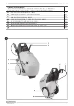
IDENTIFICATION (Fig 1)
1. Transport handle
2. Hose reel handle
3. Transport wheel
4.
On-Off switch
5. Fuel tank cap
6. High pressure lance
7. High pressure hose
8. Water outlet
9. Water inlet
OPERATION
PREPARING THE UNIT
Unpacking and completing the assembly should
be done on a flat and stable surface, with enough
space for moving the machine and its packaging,
always making use of suitable equipment.
All the fundamental parts and safety devices of
the machine are assembled by the manufacturer.
For reasons of packing and transport, some sec
-
ondary parts are supplied separately. The user
must fit these parts as explained in the instruc
-
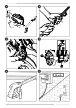
tions supplied in each assembly kit (Fig. 2, 3).
FUELING AND LUBRICATION
In the hot water high pressure cleaners a diesel
fuel burner is used for water heating.
Fuel specifications: Diesel for motors.
WARNING
Never smoke whilst refueling and keep fuel away
from all sources of fire or spark. Avoid inhaling the
fuel fumes and always refuel in outside and well ven
-
tilated areas.
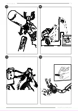
To fill the fuel tank (Fig. 4):
1.
Remove the fuel tank cap (Fig. 1.5).
WARNING
Carefully open the tank top as pressure could
have formed inside.
2.
Add fuel to the upper level of the fuel tank.
Leave a minimum 5mm of space between the
top of the fuel and the inside edge of the tank
to allow for expansion.
3.
Reposition the fuel tank cap and tighten appro
-
priately.
WARNING
Attempting to use the cleaner without fuel may
cause damage to the fuel pump.
SAFETY DEVICES
The safety devices protect the user and the appli
-
ance. The machine is factory set and all its safety
devices are sealed. It is forbidden to alter their ad
-
justment values. They must not be tampered with
or used for other than their designated purpose.
Safety valve to protect the high pressure hy
-
draulic circuit in the event of a by-pass valve mal
-
function or if the hydraulic circuit is blocked. The
safety valve is calibrated by the manufacturer and
sealed. Operations involving the safety valve must
be performed by a technical service center only.
Safety device on lance handgrip to prevents the
trigger on the handgrip from being operated ac
-
cidentally.
PWH 140 PLUS
Summary of Contents for PWH 140 PLUS
Page 4: ...4 8 10 9 11 PWH 140 PLUS...
Page 5: ...5 www ffgroup tools com 5 12 13 14 15 PWH 140 PLUS...
Page 27: ...27 www ffgroup tools com CO 0 04 nr 2 Shell Bacharach f PWH 140 PLUS...
Page 28: ...28 f f f IEC 60364 1 3kW IEC 60364 1 3mm 3 kW 30mA 30ms PWH 140 PLUS...
Page 32: ...32 50 100 200 300 500 1 2 3 4 5 14 15 1 2 PWH 140 PLUS...

