71
Step 2.
Make sure the voltage of the transmitter and receiver batteries are
acceptable levels before flying. Follow the recommendations in the radio manual
for minimum charge requirements. Charge all batteries before each flight.
Step. 3
Check trims and sub trims are set to neutral and controls centered. Check
rate and flight mode switches set properly.
If you are using MHz radio check the receiver antenna is fully extended and not
reversed on it self. Always double check to make sure your transmitter antenna is
fully extended.
Step. 4
If you are using any MHz radio you need to make sure that your
frequency is free before turning on your radio. Follow your club's pre-flight
instructions for obtaining the frequency pin.
Step 5.
With your radio system on, make sure the control surfaces are moving
correctly with each stick movement of the transmitter. Ensure all flight controls are
free from binding and are centered. Check that all hinges are tight and will not pull
out. Control linkages must be rigid and tight and have no slop.
Step 6.
The engine vibrations during flight sometimes cause bolts to vibrate
loose. Make sure the bolts holding the wing to the fuselage are in place and are
tight. Make sure all engine mounting bolts and servo screws are tight. Also make
sure the propeller nut is tight. Check all control horn bolts, wheel collars are tight
and secure. Use Thread Locker where necessary.
Step 7.
A range check is a very important pre-flight check that should be done
before the first flight of each day at the flying field. Do a range check in
accordance with the radio manufacturer instructions. If there is insufficient range
or interference do not fly until it is resolved.
Step 8.
Hold onto the airplane and move the throttle stick forward. Verify that the
motor turns the right direction and goes to full throttle. Move the throttle stick back
to low, verify that the motor stops turning. Do not fly an unreliable engine.
Step 9. Go fly and have some fun
Summary of Contents for EUROPA PRO Mini
Page 11: ...11 4 Model Assembly Process 4 1 Fuselage ...
Page 12: ...12 ...
Page 13: ...13 ...
Page 14: ...14 ...
Page 15: ...15 ...
Page 16: ...16 ...
Page 17: ...17 ...
Page 18: ...18 ...
Page 19: ...19 ...
Page 20: ...20 ...
Page 21: ...21 ...
Page 22: ...22 ...
Page 23: ...23 ...
Page 24: ...24 ...
Page 25: ...25 ...
Page 26: ...26 ...
Page 27: ...27 ...
Page 28: ...28 ...
Page 29: ...29 WARNING Before applying fuzelage balza all parts assembled PVA glue ...
Page 30: ...30 ...
Page 31: ...31 ...
Page 32: ...32 WARNING one edge balza glued CA glue ...
Page 33: ...33 ...
Page 34: ...34 ...
Page 35: ...35 ...
Page 36: ...36 ...
Page 37: ...37 WARNING Do not forget to paste the details of the hinge ...
Page 38: ...38 ...
Page 39: ...39 4 2 Wings ...
Page 40: ...40 ...
Page 41: ...41 ...
Page 42: ...42 ...
Page 43: ...43 Warning the front edge of the sand ...
Page 45: ...45 ...
Page 46: ...46 ...
Page 47: ...47 Warning 2 mm tape stuck on the support rib neu WING Warning PVA glue stained rib ...
Page 49: ...49 ...
Page 50: ...50 ...
Page 51: ...51 ...
Page 52: ...52 ...
Page 53: ...53 ...
Page 54: ...54 Warning ailerons cut and glue the balsą strips of sand at an angle of 45 degrees ...
Page 55: ...55 ...
Page 56: ...56 ...
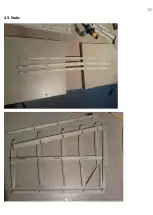
Page 57: ...57 4 3 Stabs ...
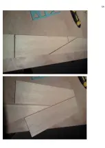
Page 58: ...58 ...
Page 59: ...59 ...
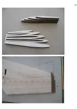
Page 60: ...60 ...
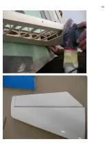
Page 61: ...61 ...
Page 62: ...62 ...
Page 63: ...63 4 4 Ruder ...
Page 64: ...64 ...
Page 65: ...65 ...
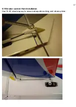
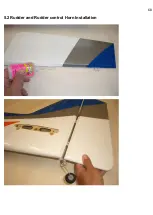
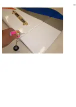
Page 68: ...68 5 2 Rudder and Rudder control Horn Installation ...
Page 69: ...69 ...

