Chapter 1
1 - 6
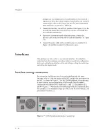
Figure 1.4, following, illustrates the back of a 520/540 controller. Note that
all ports are labeled, even those which are not intended to be used. Ports
marked with an asterisk (*) in the list following do not need to be connected
to any peripheral hardware.
*Not to be connected to any peripheral hardware.
Figure 1.4 Back view of a 520/540 controller
Environmental requirements
Before you install the controller, review the following guidelines to make
sure that you are installing and using the controller in the appropriate
environment.
General guidelines
A controller is an industrial network appliance, designed to be mounted in a
standard 19-inch rack. To ensure safe installation and operation of the unit:
•
Install the rack according to the manufacturer’s instructions, and check
the rack for stability before placing equipment in it.
•
Build and position the rack so that once you install the controller, the
power supply and the vents on both the front and back of the unit remain
unobstructed. The controller must have adequate ventilation around the
unit at all times.
•
Do not allow the air temperature in the room to exceed 40° C.
•
Do not plug the unit into a branch circuit shared by more electronic
equipment than the circuit is designed to manage safely at one time.
1. Fan
2. Power in
3. Mouse port*
4. Keyboard port
5. Universal serial bus ports*
6. Serial terminal port
7. Fail-over port
8. Video (VGA) port
9. Net1 interface (1.1)
10. Net2 interface (1.2)
11. On/off button
12 PCI expansion slots
Summary of Contents for 520
Page 1: ...Platform Guide 520 540 MAN 0067 00...
Page 2: ......
Page 4: ...ii...
Page 5: ...Table of Contents...
Page 6: ......
Page 8: ...Table of Contents iv...
Page 10: ......
Page 30: ......
Page 46: ......
Page 50: ...Chapter 3 3 4...
Page 51: ...Glossary...
Page 52: ......
Page 56: ...Glossary Glossary 4...
Page 57: ...Index...
Page 58: ......
Page 61: ......


