Chapter 4
Switch Hardware and Functionality
4 - 4
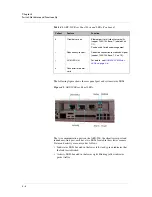
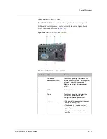
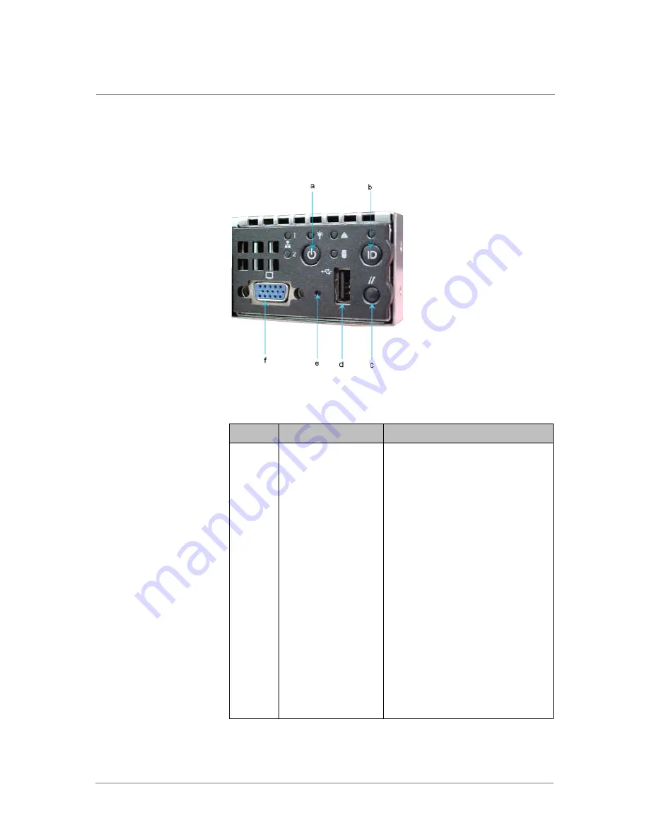
The control panel is on the right side of the front panel. Components on the
control panel are called out in the following figure; functions are described
in
Table 4.1
.
Figure 4.3
ARX-500 Front Panel Components .
Table 4.1
ARX-500 Front Panel Components and Functions
Callout
Component
Function
a
Power/sleep button
Toggles power to the device on and off.
The sleep feature is for ACPI-compatible
operating systems.
b
System ID button
Causes two ID LEDs to light: one on the
front panel and one on the rear panel.
On earlier models, the LEDs both blinked
14 times and then stopped; on newer
models, they light up until the button is
pressed again.
This is useful for locating the device.
c
Reset button
Reboots the switch.
d
USB 2.0 port
For field personnel only.
e
NMI button
Unsupported.
f
Video port
For field personnel only.
Enables the attachment of a video
monitor to the front of the chassis. You
cannot use the front and rear video ports
at the same time.
Summary of Contents for ARX-2000
Page 1: ...ARX Hardware Reference Guide MAN 0338 00 ...
Page 2: ......
Page 6: ...vi ...
Page 7: ...Table of Contents ...
Page 8: ......
Page 12: ......
Page 26: ...Chapter 1 Introduction 1 16 ...
Page 27: ...2 ARX Overview ARX Functional Overview ARX Platform Models Managing the Switch ...
Page 28: ......
Page 36: ...Chapter 2 ARX Overview 2 10 ...
Page 37: ...3 System Specifications System Specifications System Power Requirements Cable Requirements ...
Page 38: ......
Page 56: ......
Page 87: ...Index ...
Page 88: ......


