Appendix A
Removing and Replacing FRUs
A - 6
In addition, each drive has an LED to the right of the drive. The LED
flickers (blue) to indicate drive activity.
Replacing a Disk Drive
If you want to avoid a service interruption due to pulling the wrong drive or
mishandling the drive, replace the drive on the secondary (backup) switch. If
necessary, fail over the switch before starting the replacement process.
WARNING
Static electricity can damage switch components. Wear antistatic straps
before handling disk drives.
1. From the CLI, ensure that the primary switch is fully functional by
entering the
show redundancy
command.
2. From the CLI, enter the
show chassis diskuse
command to
determine the bay number of the offline or failed drive.
For example, the following output from the
show chassis diskuse
command shows two disks installed and the disk in bay 2 as
Failed
:
prtlndA>
show
chassis
diskuse
Logical
Disk
Details:
Disk
Status
Verification
Mode
Verification
Rate
‐‐‐‐‐‐ ‐‐‐‐‐‐‐‐‐‐‐‐‐‐‐‐‐‐‐‐‐ ‐‐‐‐‐‐‐‐‐‐‐‐‐‐‐‐‐ ‐‐‐‐‐‐‐‐‐‐‐‐‐‐‐‐‐
1
Optimal
Automatic
10
%
Disk
Details:
Disk
Size
State
Transfer
Rate
Model
‐‐‐‐‐‐‐‐ ‐‐‐‐‐‐‐‐‐‐‐ ‐‐‐‐‐‐‐‐‐‐‐‐‐‐‐‐‐ ‐‐‐‐‐‐‐‐‐‐‐‐‐ ‐‐‐‐‐‐‐‐‐‐‐‐‐‐‐‐‐
Bay
1
136.73G
Online
3.0Gb/sec
ST3146855SS
Bay
2
136.73G
Failed
3.0Gb/sec
ST3146855SS
3. Remove the front bezel. If necessary, see the instructions
Removing
and Re-Installing the Front Bezel, on page A-4
.
4. Loosen the thumb screw on the right hand side of the drive carrier.
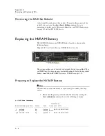
5. Slide the drive out, as shown in the following figure.
Figure A.5
Removing a Disk Drive
Summary of Contents for ARX-2000
Page 1: ...ARX 2000 Hardware Installation Guide 810 0062 00 ...
Page 2: ......
Page 6: ...vi ...
Page 7: ...Table of Contents ...
Page 8: ......
Page 11: ......
Page 12: ...Table of Contents xii ...
Page 14: ......
Page 22: ......
Page 28: ...Chapter 2 Unpacking and Installing the Switch 2 8 ...
Page 30: ......
Page 48: ...Chapter 3 Connecting the Switch to the Network 3 20 ...
Page 49: ...4 Maintenance Powering Down the ARX 2000 LED Indicators POST Diagnostics ...
Page 50: ......
Page 60: ......
Page 72: ...Appendix A Removing and Replacing FRUs A 14 ...
Page 73: ...B Installing the Rail Kit Installing the Rail Kit ...
Page 74: ......
Page 76: ...Appendix B Installing the Rail Kit B 4 ...
Page 77: ...Index ...
Page 78: ......
Page 80: ...Index Index 4 ...


