Attaching Cables and Powering On
ARX-2500 Hardware Installation Guide
2 - 13
4. Attach the power cord retention clips by gently squeezing the sides
of the clip and inserting the ends into the holes on both sides of the
power supply inlet. (Retention clips are shipped in the Accessory
Kit.)
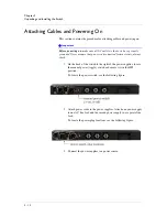
5. From the front of the switch, attach a serial console cable to the
serial console port (identified in the following figure).
6. From the back of the switch, locate the power switch and toggle it to
the
On
position.
Cabling the Client/Server Ports
You can attach cables to the client/server ports before or after the switch is
connected to the network.
F5 Networks does not supply Ethernet cables. For cable specifications and
requirements, consult the
ARX Hardware Reference Guide
.
Summary of Contents for ARX-2500
Page 1: ...ARX 2500 Hardware Installation Guide MAN 0417 00 ...
Page 2: ......
Page 6: ...vi ...
Page 7: ...Table of Contents ...
Page 8: ......
Page 10: ...Table of Contents x ...
Page 11: ......
Page 12: ...Table of Contents xii ...
Page 14: ......
Page 22: ...Chapter 1 Introduction 1 10 ...
Page 24: ......
Page 36: ...Chapter 2 Unpacking and Installing the Switch 2 14 ...
Page 38: ......
Page 55: ...4 Maintenance POST Diagnostics ...
Page 56: ......
Page 60: ......
Page 64: ...Appendix A Replacing Optical Transceivers or Chassis A 6 ...
Page 65: ...Index ...
Page 66: ......
Page 68: ...Index Index 4 ...

