Chapter 2
Unpacking and Installing the Switch
2 - 8
Installing the Bezel (optional)
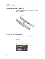
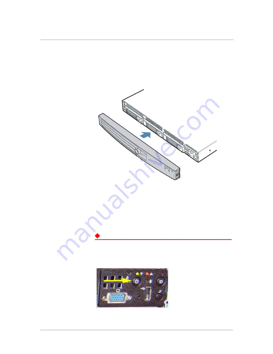
To install the optional front bezel, place it over the front panel and lock it
with one of the locking keys.
Attaching the Power Cord
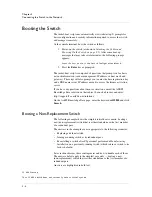
Locate the power button (shown in the following figure) on the front control
panel of the switch and ensure it is not on (power LED not illuminated).
DANGER
In the event that AC power must be removed from the system, disconnect the
power cord to avoid electric shock.
Figure 2.3
Power Button (Front View)
Summary of Contents for ARX-500
Page 1: ...ARX 500 Hardware Installation Guide 810 0039 00 ...
Page 2: ......
Page 7: ...Table of Contents ...
Page 8: ......
Page 10: ...Table of Contents x ...
Page 11: ......
Page 12: ...Table of Contents xii ...
Page 14: ......
Page 22: ......
Page 32: ......
Page 50: ...Chapter 3 Connecting the Switch to the Network 3 20 ...
Page 51: ...4 Maintenance Powering Down the ARX 500 POST Diagnostics Front Panel LEDs Rear Panel LEDs ...
Page 52: ......
Page 59: ...Index ...
Page 60: ......
Page 62: ...Index Index 4 ...


