Chapter 4
Maintenance
4 - 6
f)
System ID LED
.
Blinking blue indicates system identification is
active. No light indicates system identification is not activated.
Use this to help find the chassis in a densely-populated rack;
press the ID button on the front panel to activate the LED on the
rear panel.
Rear Panel LEDs
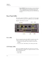
This section describes the ARX-500 rear panel LEDs. The following figure
shows the ARX-500 rear panel and its port LEDs and system status LEDs.
Figure 4.2
ARX-500 Rear Panel LEDs
Port LEDs
The two communication ports on the ARX-500, the client/server port and
redundancy-link port, have two LEDs located in their lower corners:
• Lower left. Link-status LED: steady green indicates that the link is
established.
• Lower right. Activity LED: blinking yellow indicates packet traffic.
ACM Status LEDs
There are four additional status LEDs on the right side of the rear panel.
These LEDs apply to the ACM board, as opposed to the chassis as a whole.
They have the following roles:
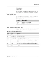
• Status (STAT)
• Alarm (ALM)
STAT
NVR
PWR
ALM
link status
activity
Summary of Contents for ARX-500
Page 1: ...ARX 500 Hardware Installation Guide 810 0039 00 ...
Page 2: ......
Page 7: ...Table of Contents ...
Page 8: ......
Page 10: ...Table of Contents x ...
Page 11: ......
Page 12: ...Table of Contents xii ...
Page 14: ......
Page 22: ......
Page 32: ......
Page 50: ...Chapter 3 Connecting the Switch to the Network 3 20 ...
Page 51: ...4 Maintenance Powering Down the ARX 500 POST Diagnostics Front Panel LEDs Rear Panel LEDs ...
Page 52: ......
Page 59: ...Index ...
Page 60: ......
Page 62: ...Index Index 4 ...

