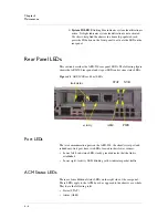
Rear Panel LEDs
ARX-500 Hardware Installation Guide
4 - 7
• NVRAM (NVR)
• Power (PWR)
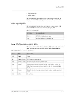
The following tables describe the states of the system status LEDs. The
System and Alert LEDs work together to determine their various states.
NVRAM (NVR) LED
The following table lists the colors and states for the non-volatile RAM
(NVRAM) LED, also known as the battery-charging LED.
Status (STAT) and Alarm (ALM) LEDs
The combined states of the Status and Alarm LEDs indicate the status of the
ACM. The following table lists these colors (status) and module states.
Table 4.1
NVRAM LED
LED Color
Description/Action
Yellow
NVRAM is in battery-backup mode.
(Off)
NVRAM is not in battery-backup mode.
Table 4.2
ACM Status and Alarm LED Patterns
Alarm
Status
Module State
(Off)
Green
Online
Red
Green (Blinking)
ACM failed or is powering down.
(Off)
Yellow (Blinking)
ACM powering up and running all POST tests.
(Off)
Yellow
Online Partial: at least one processor is online, at least one is not online yet.
If the offline processor does not come up in 5 minutes, this changes to Failed
Partial.
Red
Yellow
Failed Partial: at least one processor is online, but at least one other processor
failed.
(Off)
(Off)
Power Failure
Summary of Contents for ARX-500
Page 1: ...ARX 500 Hardware Installation Guide 810 0039 00 ...
Page 2: ......
Page 7: ...Table of Contents ...
Page 8: ......
Page 10: ...Table of Contents x ...
Page 11: ......
Page 12: ...Table of Contents xii ...
Page 14: ......
Page 22: ......
Page 32: ......
Page 50: ...Chapter 3 Connecting the Switch to the Network 3 20 ...
Page 51: ...4 Maintenance Powering Down the ARX 500 POST Diagnostics Front Panel LEDs Rear Panel LEDs ...
Page 52: ......
Page 59: ...Index ...
Page 60: ......
Page 62: ...Index Index 4 ...

