Chapter 7
Connecting the Switch to the Network
7 - 4
Connect the console terminal to the serial Console port (RJ-45) on the SCM.
An RJ-45 to DB9 adapter is included in the installation kit if you want to
connect to your management station’s serial DB9 port.
Booting the Switch
The
initial-boot script
runs automatically at switch start-up. It prompts for
basic configuration and security information required to access the switch
and manage it remotely.
At the console terminal, boot the switch as follows:
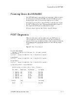
1. Power-on the switch (as shown in
Powering Up the Chassis
, on
page 6-12). After some boot-up messages, the following prompt
appears:
Press
<Enter>
to
start
the
Switch
Configuration
Wizard.
2. Press
<Enter>
as prompted.
Several questions appear, prompting you for basic network information
(such as management-IP address, mask, and gateway). These questions
comprise the initial-boot script. Answer these questions as they come up.
Examples and instructions appear in the subsections below.
Sample: Booting a Non-Replacement Switch
This sample shows the simplest initial-boot scenario, for a new
(non-replacement) switch that is either standalone or the
first
member of a
redundant pair. The sample answers are not necessarily appropriate to the
following scenarios:
• this replaces a defunct switch,
• this will join a running switch as its redundant peer, or
• this switch is being re-installed after F5 personnel performed a
“Manufacturing Installation” on a previously-running switch.
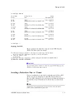
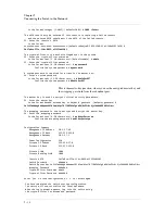
Later sections discuss these contingencies and how to handle each of them.
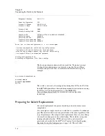
The answers below apply to the simplest case only. Sample answers are
shown in bold text:
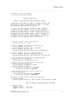
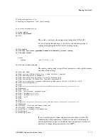
F5
ARX
Switch
Startup
This
F5
ARX
switch
does
not
currently
have
critical
system
information
programmed.
The
following
wizard
prompts
you
for
this
information.
You
can
connect
to
the
switch
through
the
out
‐
of
‐
band
management
interface
when
you
finish.
To
restart
the
configuration
program,
enter
'r'
at
any
prompt.
Acknowledge
acceptance
of
the
following
terms
and
conditions
Summary of Contents for ARX 6000
Page 1: ...ARX 6000 Hardware Installation Guide 810 0001 00 ...
Page 2: ......
Page 5: ...Table of Contents ...
Page 6: ......
Page 10: ...Table of Contents x ...
Page 12: ......
Page 22: ...Chapter 1 1 12 ...
Page 24: ......
Page 30: ......
Page 36: ...Chapter 3 Chassis Hardware 3 8 ...
Page 38: ......
Page 46: ......
Page 52: ......
Page 66: ......
Page 80: ......
Page 87: ...A Cable Connectors ARX 6000 Connectors Console Connector and Pinouts SFP Optical Connector ...
Page 88: ......
Page 92: ...Appendix A Cable Connectors A 6 ...
Page 94: ......
Page 100: ...Appendix B Removing and Replacing FRUs B 8 ...
Page 101: ...Index ...
Page 102: ......

