Important: In the event that network access is impaired or not yet configured, the serial console might be
the only way to access the unit. You should perform all installations and upgrades using the serial console,
as these procedures require reboots, in which network connectivity is lost temporarily.
1.
If you are using the default network configured on the management interface, connect an Ethernet cable
to the management port.
Note: For EMI compliance, shielded cables are required for the management port, and the shield must
be grounded at both ends.
2.
Connect the console port to a serial console server. Depending on which F5 system you have and the
console network to which you are attaching, you can use either the supplied RJ45 to DB9 console port
cable or the RJ45F to RJ45M rolled serial adapter to connect the system to a serial console.
•
Connect the RJ45 to DB9 console port cable to the console port on the system.
Note: The default baud rate and serial port configuration is 19200/8-N-1.
•
Connect the RJ45F to RJ45M rolled serial adapter to the console port if you are connecting the
system to a serial console server with a standard CAT5 cable, and then connect the CAT5 cable to
the adapter. The adapter provides the appropriate pinout connection to your equipment. For information
about cable and connector pinout specifications, see
F5 Platforms: Accessories
at
techdocs.f5.com/kb/en-us/products/big-ip_ltm/manuals/product/f5-plat-accessories.html
.
Figure 7: The RJ45F to RJ45M rolled serial (pass-through) adapter (CBL-0143-00)
3.
Connect power to installed power supplies:
Note: Be sure to route the power cords away from the fan tray so that the cords do not impede access
to it.
•
For AC-powered systems, connect an auto locking power cable to the power input panel on all
installed power supply units (PSUs), and then connect the cable to the power source.
Note: Not all country-specific power cables include a locking feature.
Note: To remove the locking power cord, pull one or both of the power cord locking tabs away from
the supply.
•
For DC-powered systems, connect a DC cable to each supply and then connect the cable to your DC
mains power source.
14
Platform Installation
Summary of Contents for i15000 Series
Page 1: ...Setting Up the i15000 Series Platform MAN 0661 02 ...
Page 2: ......
Page 4: ...4 Table of Contents ...
Page 8: ......
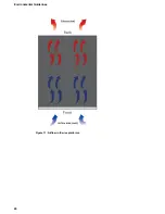
Page 24: ...Figure 11 Airflow in iSeries platforms 24 Environmental Guidelines ...
Page 26: ......


