background image

Guidelines for NEBS platforms

This information applies to the Network Equipment-Building System (NEBS) version of the this platform:

This equipment meets NEBS requirements per GR-63-CORE.

This equipment is suitable for installation in these locations:

Network Telecommunication Facilities

Locations where the National Electrical Code (NEC) applies

Important: The intra-building interfaces of this platform, including Ethernet, are suitable for connection
to intra-building or unexposed wiring or cabling only with shielded and grounded cables at both ends. The
intra-building ports of the equipment must not be connected metallically to interfaces that connect to the
outside plant (OSP) or its wiring.

Note: You should coat bare conductors with an appropriate antioxidant compound before you make crimp
connections. You should bring all unplated connectors, braided strap, and bus bars to a bright finish and
then coat them with an antioxidant before you connect them.

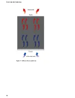
Platform airflow diagram

When you install the platform into a rack, it is important to understand the unit's airflow direction so that
you can ensure proper cooling.

The platform employs a negative pressure fan system, which draws cold air in from the front of the chassis.

23

Setting Up the i15000 Series Platform

Summary of Contents for i15000 Series

Page 1: ...Setting Up the i15000 Series Platform MAN 0661 02 ...

Page 2: ......

Page 3: ...000 N NEBS platform to the rack 11 About grounding the platform 12 Connect the ground lug to the ground terminal 13 Connect the cables and other hardware 13 Configure a management IP address using the LCD 15 License the platform 18 Environmental Guidelines 19 General environmental and installation guidelines 19 Chassis rack mount spatial requirements 20 Guidelines for power supply units PSUs 21 Gu...

Page 4: ...4 Table of Contents ...

Page 5: ...ion please see the data sheet at www f5 com pdf products big ip platforms datasheet pdf About the platform Before you install this platform review information about the controls and ports located on both the front and back of the platform On the front of the platform you can use the LCD touchscreen to view information about manage and reset the system You can also use the front panel LEDs to asses...

Page 6: ... Chassis ground terminals Figure 4 Back view of the i15000 Series DC powered platform 1 Fan tray removable 2 Power input panel 1 DC terminal 3 Power input panel 2 DC terminal 4 Chassis ground terminals Hardware included with the platform This platform includes all of the hardware components listed here Hardware Quantity Power cables black AC power only per platform configuration Might include mult...

Page 7: ... You can use either 10000 Megabit switches with a breakout cable or 40 100 Gigabit Ethernet switches You can use any USB certified CD DVD mass storage device or a USB flash drive for installing upgrades and for system recovery Note External CD DVD drives must be externally powered External USB CD DVD drive or USB flash drive You can remotely manage the platform by connecting to a serial console te...

Page 8: ......

Page 9: ...hip the platform later About the quick install rails The quick install rails are optimized for installation into square hole cabinets but can be installed in other cabinet styles such as round hole cabinets using the screws provided The rails are easily converted to mount to either cabinet style Figure 5 Quick install rails For information about installing the platform using the quick install rail...

Page 10: ... rail lock brackets to each side of the unit using two of the black M3 x 8mm flathead screws that are provided with the kit Use 5 inch pounds 0 6 Newton meters of torque on these screws 2 Slide the unit into the rack Warning Due to the weight of the platform at least two people are required to install this chassis into a rack Failing to use two people can result in severe personal injury or equipm...

Page 11: ...ines to make sure that you are installing the platform into a compatible rack and in the appropriate environment Note F5 recommends that you keep all original packaging in case you need to repackage and ship the platform later Secure the i15000 N NEBS platform to the rack Be sure that the quick install rails and rail lock brackets are installed onto the chassis before you secure the unit in the ra...

Page 12: ...emoved to perform service or installation procedures You can connect other bonding or grounding conductors to a grounding connector provided a reliable bond between the connector and the equipment is not disturbed during installation service or maintenance of the platform For this platform F5 recommends using dual ring grounding lugs by Panduit part number LCDX6 10AF L Important All grounding cabl...

Page 13: ... provide power to the system you need to connect the grounding hardware 1 Remove the M4 Keps nuts from the ground lug on the back of the chassis 2 Attach a ground ring terminal to the 6 AWG copper ground wire 3 Install the ground ring terminal onto the chassis ground terminal 4 Secure the ground ring terminal with the M4 Keps nuts Use 18 to 24 inch pounds 2 0 to 2 7 Newton meters of torque on thes...

Page 14: ...200 8 N 1 Connect the RJ45F to RJ45M rolled serial adapter to the console port if you are connecting the system to a serial console server with a standard CAT5 cable and then connect the CAT5 cable to the adapter The adapter provides the appropriate pinout connection to your equipment For information about cable and connector pinout specifications see F5 Platforms Accessories at techdocs f5 com kb...

Page 15: ...stem into a single file that you can provide to F5 Technical Support to aid in troubleshooting For more information see K12878 Generating diagnostic data using the qkview utility Configure a management IP address using the LCD You can use the touchscreen LCD to configure the management IP address With the management IP address you can access the BIG IP Configuration utility to configure other aspe...

Page 16: ...If you are using IPv6 and or IPv4 you can configure the management IP address manually Note As of BIG IP software version 14 0 you can configure your system to be managed concurrently from an IPv4 and an IPv6 address a Tap DHCP The DHCP screen displays b Make sure that the DHCP option is set to OFF If the DHCP option was set to ON tap OFF and then tap Commit to save the change c Tap Back to return...

Page 17: ...of the routing prefix for the IPv4 or IPv6 management IP address For an IPv4 address this screen displays For an IPv6 address this screen displays f Tap Commit to save your changes g On the Management screen swipe to scroll down and tap Gateway h Use the left right up and down arrows to configure the default route for the management interface 17 Setting Up the i15000 Series Platform ...

Page 18: ...IP address that you assigned https mgmt ip address For example type an IPv4 management IP address like this https 192 168 0 22 For an IPv6 management address of 2001 0DB8 f5f5 64 type the address like this https 2001 0DB8 f5f5 2 Type admin as the user name and admin as the password If this is the first time you have accessed the Configuration utility the first screen you see is the Introduction sc...

Page 19: ... not allow the air temperature in the room to exceed 104 F 40 C Note GR 63 CORE NEBS compliant shelf units can operate at maximum air temperature of up to 131 F 55 C Operation at the maximum temperature is supported on a short term basis per GR 63 CORE Do not plug the unit into a branch circuit shared by more electronic equipment than the circuit is designed to manage safely at one time Route and ...

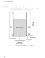
Page 20: ...orms ship with a rack mount kit to help install the system more easily This kit requires that the rack or cabinet has certain clearances and spacing as shown here Figure 8 Rack mounting spatial requirements for the i15000 Series platform 20 Environmental Guidelines ...

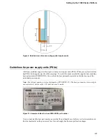
Page 21: ...can find the base part number printed on the label on top of the individual power supply Note The full part number is a nine digit number PWR XXXX YY The base part number is seven digits and must match but the suffix YY does not need to match Figure 10 Example of label to check PWR XXXX part number If you cannot read the base part number ensure that the pull handles are both in a vertical orientat...

Page 22: ...her or not the socket outlet from which the equipment is to be powered provides a connection to the building protective earth If not the SERVICE PERSON shall arrange for the installation of a PROTECTIVE EARTHING CONDUCTOR from the separate protective earthing terminal to the protective earth wire in the building Caution High leakage current Earth connection essential before connecting supply Guide...

Page 23: ...es at both ends The intra building ports of the equipment must not be connected metallically to interfaces that connect to the outside plant OSP or its wiring Note You should coat bare conductors with an appropriate antioxidant compound before you make crimp connections You should bring all unplated connectors braided strap and bus bars to a bright finish and then coat them with an antioxidant bef...

Page 24: ...Figure 11 Airflow in iSeries platforms 24 Environmental Guidelines ...

Page 25: ...ate and reliable However F5 assumes no responsibility for the use of this information nor any infringement of patents or other rights of third parties which may result from its use No license is granted by implication or otherwise under any patent copyright or other intellectual property right of F5 except as specifically described by applicable user licenses F5 reserves the right to change specif...

Page 26: ......

Page 27: ...onnecting to ground terminal 13 locating 12 location 5 guidelines battery replacement 19 H hardware AC powered equipment 22 DC powered equipment 22 hardware requirements for peripherals 7 hard wired failover 13 hubs 7 I i15000 N NEBS platform securing 11 indicator LEDs location 5 installation guidelines 19 performing using serial console 7 recommendations for 19 spacing between units 19 L LCD remo...

Page 28: ...ines 19 quick install rail kits for 9 rack mount spatial requirements for 20 rail lock brackets installing 10 rail mount installing rail lock brackets 10 redundancy for system 13 redundant system configuration 13 See also device service clustering DSC remote administration 7 RJ45F to RJ45M rolled serial adapter 13 S serial console for hardware installation 7 hardware installation of 13 serial fail...

Reviews: