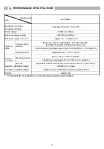
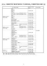
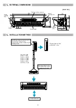
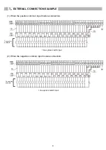
background image


7

EXTERNAL CONNECTION EXAMPLE   


(1) When the positive common input module connection. 


(2) When the negative common input module connection. 


1 line system switch input 

1 line system switch input 

Connection 
example 

Connection 
example 

Summary of Contents for FA-TB32XY

Page 1: ...is product only For programmable controller system safety precautions refer to the User s Manual of the programmable controller to be used In this manual the safety precautions are classified into two levels WARNING and CAUTION WARNING Indicates that incorrect handling may cause hazardous conditions resulting in death or severe injury CAUTION Indicates that incorrect handling may cause hazardous c...

Page 2: ...ue to noise Installation Precautions WARNING Shut off the external power supply all phases before installation Failure to do so may result in electric shock Installation Precautions CAUTION Use the programmable controller in an environment that meets the general specifications in this User s Manual Failure to do so may result in electric shock fire malfunction or damage to or deterioration of the ...

Page 3: ...ction Tighten the connector screws within the specified torque range Undertightening can cause short circuit fire or malfunction Overtightening can damage the screw and or module resulting in drop short circuit fire or malfunction Install the connector to the module securely Failure to do so may cause malfunction When disconnecting the cable from the module do not pull the cable by the cable part ...

Page 4: ...lure to do so may cause malfunction Shut off the external power supply for the system in all phases before mounting or removing the module Failure to do so may cause the module to fail or malfunction or damage After the first use of the product do not mount remove the module and the cable more than 50 times IEC 61131 2 compliant respectively Exceeding the limit of 50 times may cause malfunction St...

Page 5: ...tion resistance Under continuous vibration 57 to 150Hz 4 9m s2 0 5G Shock resistance Conforms to JIS B 3502 and IEC61131 2 147m s2 15G 3 times each in X Y and Z axis directions Operating atmosphere There should be no corrosive gases Operating altitude 1 2 000m or lower Installation location Inside control panel Overvoltage category 2 II or lower Pollution level 3 2 or lower 1 Do not use or store i...

Page 6: ...4P 7 62mm pitch Self tightening screw with finger protector cover Terminal block Screws Terminal screw tightening torque range 58 8 to 88 2N cm 6 to 9kgf cm Terminal block Applicable wire Applicable wire 0 5 to 1 25mm2 M4 0 7mm 12mm or greater Mounting screws Tightening torque range 78 to 118N cm 8 to 12kgf cm Module mounting DIN rail Applicable DIN rail TH35 7 5Fe TH35 7 5Al conform to JIS C 2812...

Page 7: ...NT1P FA CBL FMV A1SX41 Note 2 A1SX41 S1 A1SX41 S2 A1SX42 Note 2 A1SX42 S1 A1SX42 S2 FA CBL FMV At positive common FA CBL FMV A1SX71 Note 1 Note 2 At negative common FA CBL FMVE A1SX81 Note 2 A1SX81 S2 FA CBL DMFX A1SX82 S1 FA CBL FMVE A1SY41P Note 2 A1SY42P Note 2 A1SY71 Note 1 Note 2 FA CBL FMV A1SY81 Note 2 FA CBL DMFY A1SY82 Note 2 FA CBL FMV MELSEC AnS Series connector type A1SH42 Note 2 A1SH4...

Page 8: ...or Insert the connector to the back and then fully install the connector to the programmable controller module using the mounting screws Programmable controller module QX41 other Insert the connector to the back and then fully secure the connector with a clip Connection cable FA CBL FMV FA CBL FMVE FA CBL DMFX FA CBL DMFY FA CBL FMH FA FCBL FMH Sensor load etc ...

Page 9: ... CONNECTION EXAMPLE 1 When the positive common input module connection 2 When the negative common input module connection 1 line system switch input 1 line system switch input Connection example Connection example ...

Page 10: ...10 3 When the sink output module connection 4 When the source output module connection 1 line system load 1 line system load Connection example Connection example ...

Page 11: ...11 8 APPLICABLE CRIMPING TERMINALS Size of crimping terminal Terminal trapezoid Size of crimping terminal A B MIN 5 0 MAX 6 3 Unit mm Unit mm ...

Page 12: ...roduct shall be systematically provided with backup and fail safe functions when applied to equipment that may lead to a major accident or damage in the unlikely event any failure or defect should occur in the product 1 13 5 Kudankita Chiyoda ku Tokyo Japan 102 0073 Homepage URL http www mee co jp Direct any technical inquiries to Nagoya office PC Engineering Dept Phone 81 52 723 8058 Fax 82 52 72...

Reviews: