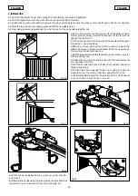
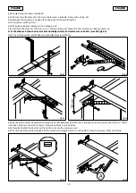
background image

22

ENGLISH

ENGLISH

9. CONNECTIONS

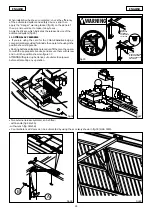
9.1 Connect the power cable, as shown in figure 31, securing it with a clamp in the indicated area.

9.2 Fit the screw in the appropriate seat and tighten with washer
and nut (fig.31 ref.A).

9.3 Position the earth eyelet on the screw, add a  washer and
tighten wit the nut (fig. 32 ref.A).

9.4 If you are using tube sleeves to secure the cables, make a slot
as shown in figure 32.

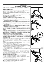
9.5 Screw the lamp in the appropriate lamp-holder.

9.6  Secure the operator housing using appropriate screws (fig.33).

Fig.31

A

Fig.32

A

Fig.33

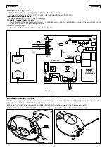
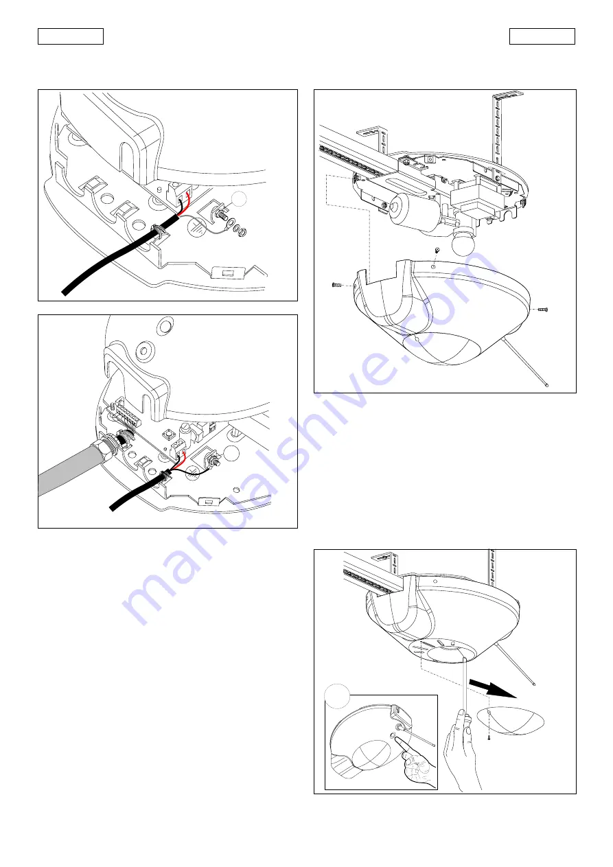
To  access the programming push-button, dismantle the cour-
tesy light ceiling fixture, unscrewing the appropriate screw.
Slide the ceiling fixture in the direction shown by the arrow (fig.34).
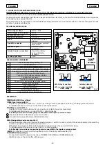
INITIAL SET-UP

The obstacle detector does NOT operate during this initial
procedure – this  means that the operator is using  the motor’s
maximum power to move the door.
Further, the Fail-safe procedure is not active.
The set-up procedure enables you to establish the following:
- anti-crushing safety levels at  opening and closing.
- deceleration points
- operator’s  fully open and fully closed points
- pause interval
This procedure can be carried out at any time, with the operator
in any position.
Two function logics are available on this appliance:
AUTOMATIC (TABLE 1)
SEMI-AUTOMATIC (TABLE 2)

10. PROGRAMMING

Fig.34

A

Summary of Contents for 525

Page 1: ...nt amendments 91 368 EEC 93 44 EEC and 93 68 EEC complies with the essential safety requirements in the following EEC Directives 73 23 EEC and subsequent amendment 93 68 EEC 89 336 EEC and subsequent...

Page 2: ...temsweredesignedandbuilt for indoor use and for controlling vehicle access Avoid any other use 2 DIMENSIONS Fig 1 Fig 2 Power pipe 230V Cable 4 x 0 5 RX photocell Cable 3x0 5 Radio receiver Cable 2 x...

Page 3: ...by the automatic system Check if an efficient earth plate is available for electrical connection to the operator Make sure there is a clearance of at least 35 mm between the ceiling and the highest sl...

Page 4: ...e advise you to use the optional guide fig 8 ref B fitting it on the central slide fig 8 ref C 5 3 Insert the longitudinal member with chain in the central slide fig 9 until it meets the metal project...

Page 5: ...N B To apply tension to the chain turn the nut clock wise To slacken the chain turn the nut anti clock wise Warning too much chain tension could damage the motor unit 5 6 Offer the assembled guide to...

Page 6: ...spect to the door use a spirit level 6 8 When you have reached the correct position measure the distance between ceiling and operator so that you can shape the securing brackets in advance 6 9 Fit the...

Page 7: ...distance between drive bracket and sliding rail bracket must not exceed 20cm max 30 fig 24 6 22 Check the position drill and secure with suitable screws fig 24 Fig 25 LOCK Fig 26 6 23 Re lock the aut...

Page 8: ...Open push button P2 Set up push button LK1 Enable disable fail safe LK2 Varies sensitivity of reversing device Fig 27 fail safe enabled fail safe disabled LK1 reversing sensitivity 150N 15Kg LK2 rever...

Page 9: ...es to vary the sensitivity of the reversing device fig 27 Fig 28 OTHERSAFETYDEVICES STOP OPEN 8 ANTENNAINSTALLATION OPTIONAL 8 1 If you are using an RP receiver and wish to increase its range you can...

Page 10: ...ing push button dismantle the cour tesy light ceiling fixture unscrewing the appropriate screw Slidetheceilingfixtureinthedirectionshownbythearrow fig 34 INITIAL SET UP The obstacle detector does NOT...

Page 11: ...tronic appliance establishes the deceleration points and pause time is fixed at 3 minutes If the SETUP procedure was successful the courtesy lamp stays lightedfor5seconds Duringthistime inordertoreduc...

Page 12: ...tomated system and safety devices and then apply the danger warning sticker fig 35 on the panel of the up and over door to make it easy to see Apply the sticker which indicates the release device of t...

Page 13: ...n electronic device ensures that any obstacles are detected The door is normally closed when the electronic control unit receives an opening commandfromtheremotecontrol orfromanyothertypeofpulsegenera...

Reviews: