


USER’S GUIDE
AUTOMATIC SYSTEMS 525-530
Read the instructions carefully before using the product and store them for future use.
GENERAL SAFETY REGULATIONS
If correctly installed and used, 525-530 automatic systems ensure a high degree of safety.
Some simple rules on behaviour can prevent accidental trouble:
- Do not, under any circumstances, stand under the overhead door.
- Do not allow children, persons or things near the automatic systems, especially while
they are operating.
- Keep remote-controls, or other pulse generators that could open the door, well away
from children.
- Do not allow children to play with the automatic system.
- Do not willingly obstruct door movement.
- Prevent any branches or shrubs from interfering with door movement.
- Keep the indicator-lights efficient and easy to see.
- Do not attempt to activate the door by hand unless you have released it.
- In the event of malfunctions, release the door to allow access and wait for qualified
technical personnel to do the necessary work.
- When you have set manual operation mode, cut power to the system before restoring
normal operation.
- Do not in any way modify the components of the automation system.
- Do not attempt any kind of repair or direct action whatever and contact qualified
FAAC personnel only.
- At least every six months: arrange a check by qualified personnel of the automatic
system, safety devices and earth connection.
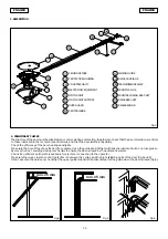
DESCRIPTION
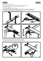
Automatic systems 525-530 are designed to automate overhead spring-balanced,
sectional, counterbalanced (with special GDA 3000 accessory) doors for residential
garages.
The automatic systems consist of an electro-mechanical operator, electronic control
appliance, courtesy lamp and protection housing built into a single unit.
The system is non-reversing and, therefore, the door locks mechanically when the motor
is not operating and, consequently, no other lock is necessary; a manual release makes
it possible to move the door in case of a power cut or fault.
An electronic device ensures that any obstacles are detected.
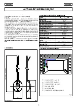
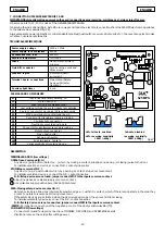
The door is normally closed; when the electronic control unit receives an opening
command from the remote control, or from any other type of pulse generator (fig.1), it
activates the electric motor which, by means of a transmission chain, pulls the door
open to allow access.
-If the automatic mode was set, the door closes automatically after pause time has
elapsed.
An opening pulse supplied during opening has no effect.
-If the semi-automatic mode was set, a second pulse must be sent to close the door
again.
An opening pulse supplied during opening stops movement.
An opening pulse supplied during re-closing, always causes movement to be reversed.
A stop pulse (if supplied) always stops movement.
For full details of door activity in the different logics, consult the installation engineer.
Automatic systems may include safety devices (photocells) that prevent the door from
closing when there is an obstacle in the area they protect.
Emergency manual opening is possible by using the release system.
The warning-light indicates that the door is currently moving.
The courtesy light is activated when the motor starts and continues for about 2 minutes
after it stops.
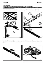
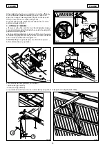
MANUAL OPERATION
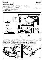
The 525-530 operators are equipped with an emergency system activated from the inside
– however, a lock can be fitted on request, for activating release from the outside.
If the door has to be moved manually due to a power cut or a fault of the automatic
system, use the release device as follows:
- Release the operator, by pulling the release lever downward (fig.22 ref.A).
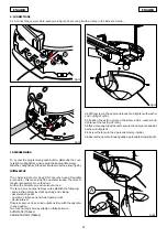
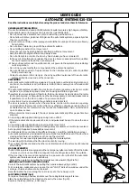
RESTORING AUTOMATIC OPERATION MODE
Re-lock the automatic system by pulling the handle sideways (fig.2 ref.B):
N.B.: on release, make sure you can see the red “LOCK” indication window under the
carriage – this means it was correctly reset.
Important: slide the door along the rail to re-locate the hook-up point.
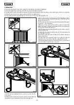
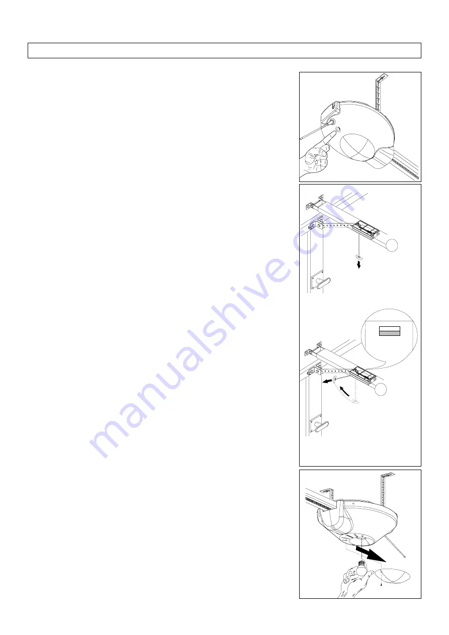
LAMP REPLACEMENT (fig.3)
To replace the lamp, unscrew and remove the ceiling fixture support screw.
Slide the ceiling fixture in the direction shown by the arrow (fig.33).
Replace the lamp (220Vac , 40W max.).
Fig.2
Fig.3
Fig.1
A
B
LOCK
RELEASE
RE-LOCK


