


14
ENGLISH
ENGLISH
AUTOMATIC SYSTEM 525/530
These instructions apply to the following models:
525 - 530
Automatic systems 525-530 are designed to automate overhead
spring-balanced, sectional, and counterbalanced (with special
GDA 3000 accessory) doors for residential garages.
They consist of an electro-mechanical operator, electronic con-
trol appliance and courtesy lamp built into a single unit. The unit
is fitted to the ceiling and opens the door by means of a
transmission chain.
The system is non-reversing and, therefore, the door locks me-
chanically when the motor is not operating and, consequently,
no other lock is necessary; two manual releases on the inside and
outside (optional) make it possible to move the door manually in
case of a power cut or fault.
Any obstacles are certain to be detected by a controlling
electronic device which comes into action while the automatic
system is in operation.
The 525 and 530 automated systems were designed and built for
indoor use and for controlling vehicle access.Avoid any other
use.
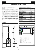
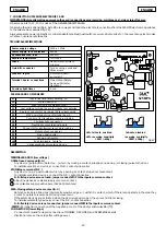
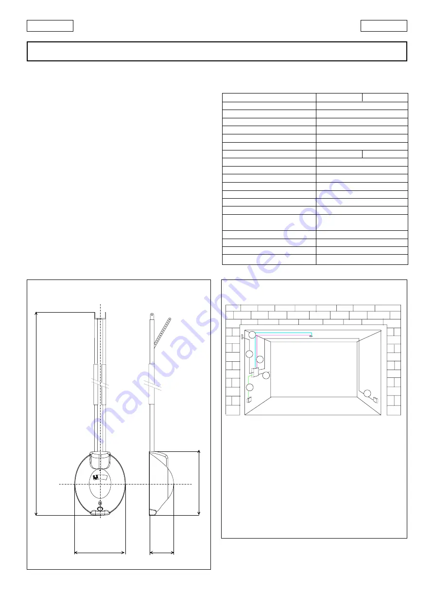
2. DIMENSIONS
Fig.1
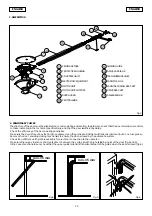
Fig.2
Power pipe (230V)
Cable 4 x 0,5 (RX photocell)
Cable 3x0.5 (Radio receiver)
Cable 2 x 0,5 (TX photocell)
Low voltage pipe
Cable 2 x 1.5 + earth (power supply)
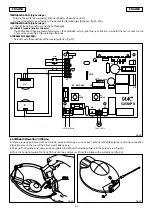
3. ANCILLARY ELECTRICAL EQUIPMENT
1. DESCRIPTION AND TECHNICAL SPECIFICATIONS
328
157
415
2738 (525)/ 3338 (530)
Dimensions in mm
1
2
3
4
5
6
MODEL
525 530
Power supply
230V ac 50Hz
Electric motor
24V dc
Maximum absorbed power
220W
Maximum cycles per hour
20 (with load of 28Kg at 20°C)
Maximum consecutive cycles
6 (at 20°C)
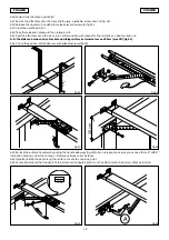
Minimum distance from ceiling
35mm (Fig.4 and 5 )
Maximum available travel
1900mm
2500mm
Pulling/thrust power
600N (~60Kg)
Courtesy light
230V ac 40W max
Courtesy light timer
2 minutes
Carriage speed (load free)
12 cm/sec.
Deceleration speed
6 cm/sec.
Deceleration travel
Varies according to setup
Internal safety device
Type 2
Response time of built-in safety
150msec
device
Door max width
3000 mm (5000mm sectional)
Door max height
See max available travel
Protection class
IP20
Ambient temperature
-20 / +55°C


