


16
ENGLISH
ENGLISH
Fig.10
Fig.11
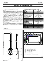
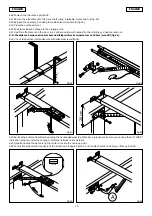
5. OPERATOR ASSEMBLY
N.B.: Screws and expansion plugs for securing the operator to the infrastructure are not supplied.
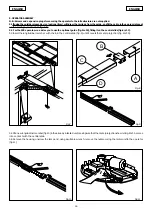
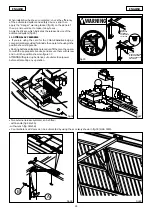
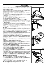
5.1 If using the outside release device (optional item), withdraw the carriage from the guide, and fit the cable in the appropriate seat
on the carriage, as shown in figure 7.
5.2 For the 530 operator, we advise you to use the optional guide (fig.8 ref.B), fitting it on the central slide (fig.8 ref.C).
5.3 Insert the longitudinal member with chain in the central slide (fig. 9) until it meets the metal projection (fig.8 ref.D).
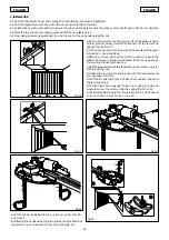
5.4 Fit a new longitudinal member (fig.10) in the already installed unit, making sure that the metal projection shown in Fig. 8 ref.A comes
into contact with the central slide.
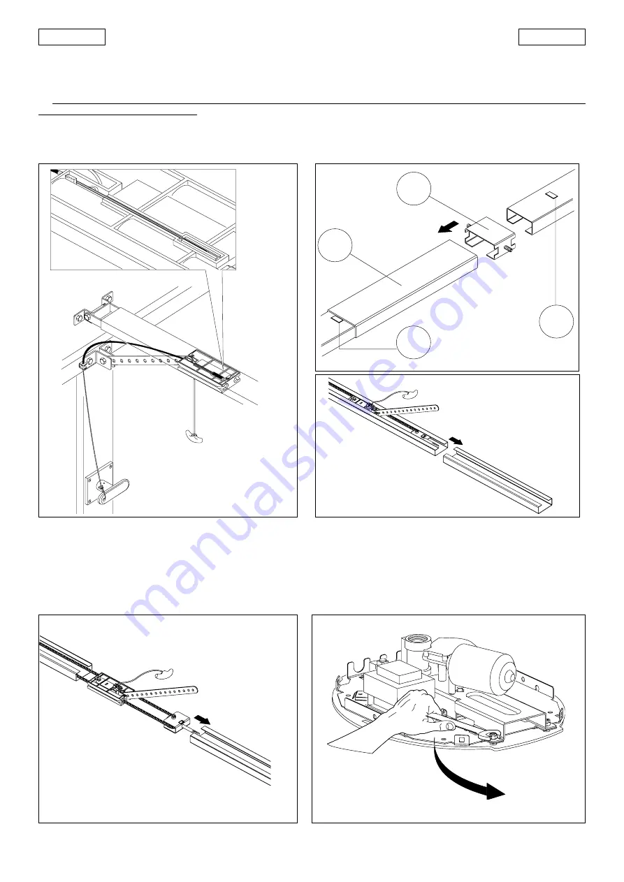
5.5 Remove the housing, unscrew the lamp and, using a suitable wrench, remove the nuts securing the motor unit to the operator
(fig.11).
Fig.9
Fig.8
Fig.7
A
B
C
D


