


19
ENGLISH
ENGLISH
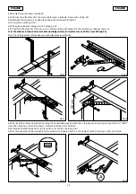
6.16 For sectional doors, see point 6.25.
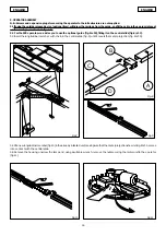
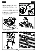
6.17 Secure the attachment to the drive shaft, using a suitable screw and nut (fig. 22).
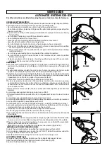
6.18 Release the operator, by pulling the release lever downward (fig.23).
6.19 Close the overhead door.
6.20 Take the released carriage to the closing point.
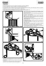
6.21 Rest the attachment on the door, in a central position with respect to the mid-line you had marked out.
N.B.: The distance between drive bracket and sliding rail bracket must not exceed 20cm (max 30°) (fig.24).
6.22 Check the position, drill and secure with suitable screws (fig.24).
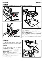
Fig.25
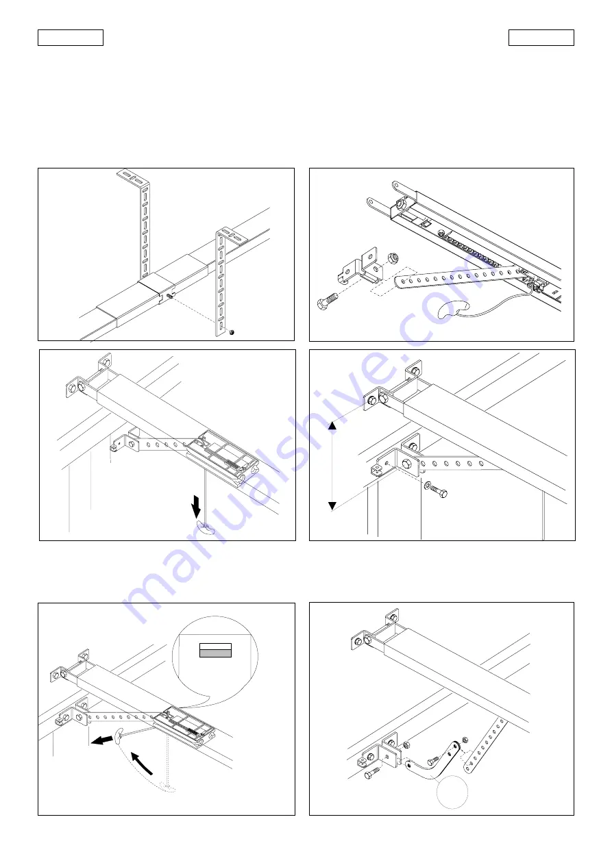
LOCK
Fig.26
6.23 Re-lock the automatic system by pulling the handle sideways (fig.25) N.B.: on release, make sure you can see the red “LOCK”
indication window under the carriage – this means it was correctly reset.
6.24 Important: slide the door along the rail to re-locate the hook-up point.
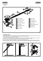
6.25 For sectional doors that require it, fit the arm shown in figure 26 ref. A on the attachment and carry on from point 6.18.
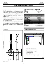
Fig.21
Fig.22
Fig.23
Fig.24
20 cm
A


