


15
ENGLISH
ENGLISH
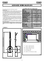
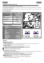
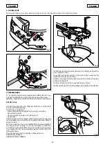
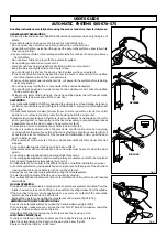
3. DESCRIPTION
4. PRELIMINARY CHECKS
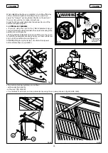
The structure of the door must be suitable for accommodating automation. In particular, check that the door dimensions conform
to those indicated in the technical specifications, and that the door is sufficiently sturdy.
Check the efficiency of the door bearings and joints.
Make sure the door is free of any friction; if necessary, clean the guides and oil them with silicone lubricant, but do not use grease.
Remove the door’ s existing closing mechanism to ensure the door is closed by the automatic system.
Check if an efficient earth plate is available for electrical connection to the operator.
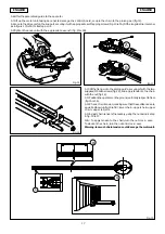
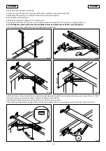
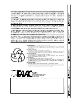
Make sure there is a clearance of at least 35 mm between the ceiling and the highest sliding point of the door (fig.4 and 5).
Fig.4
Fig.5
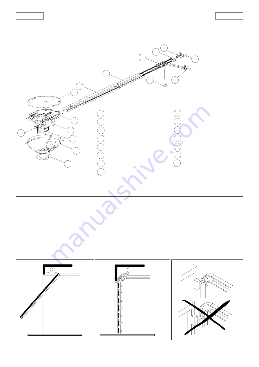
Fig.6
In the case of sectional doors, check that the upper guide roller is in the horizontal part of the guide when the door is closed (fig.6).
Fig.3
1
10
9
8
7
6
5
3
2
13
12
11
3
4
14
15
1
2
3
4
5
6
7
9
10
11
12
13
14
8
15
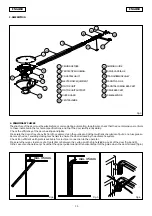
CEILING FIXTURE
MOTOR UNIT
ELECTRONIC EQUIPMENT
COURTESY LIGHT
PROTECTIVE HOUSING
SLIDING GUIDE
DUST-GUARD
RELEASE KNOB
DRIVE BRACKET
FRONT SECURING BRACKET
FRONT FLANGE
TRANSMISSION PULLEY
DRIVE CARRIAGE
MOTOR UNIT SUPPORT
CENTRAL SLIDE
min. 35 mm
min. 35 mm
Summary of Contents for 565
Page 15: ......


