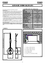
background image

18

ENGLISH

ENGLISH

6. INSTALLATION

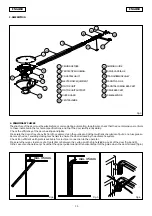
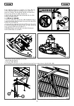
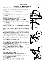
6.1 Find the mid-point of door and ceiling and mark the two lines with a highlighter.

6.2 Find the highest movement point of the door and mark this on the lintel.

6.3 Position the securing bracket 5 mm above the line you had marked, which must be centered with respect to the door (fig.16).

6.4 Mark the two bracket securing points and drill the necessary holes.

6.5 Next, using screws and washers, screw the bracket on the expansion plugs (fig. 16).

Fig.19

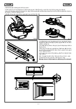
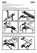
6.6 Place the operator on the ground, lift up the sliding longitu-
dinal member and step toward the bracket – fit the screw and
tighten the nut (fig. 17).

6.7 Lift up the operator, making sure it is horizontal with respect
to the door – use a spirit level.

6.8 When you have reached the correct position, measure the
distance between ceiling and operator so that you can shape
the securing brackets in advance.

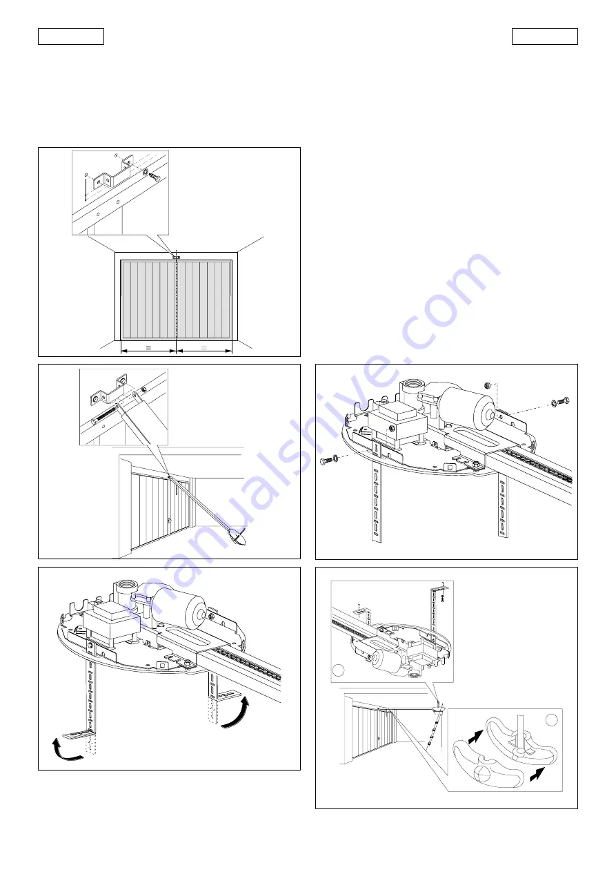
6.9 Fit the supplied brackets in the slots and secure the operator
with the nut (fig. 18).

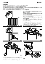
6.10 Bend the securing brackets in line with the measurements
you had taken (fig. 19).

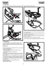
6.11 Lift up the operator, place it in its correct position, and mark
the securing holes.

6.12 Drill, insert the expansion plugs and, using screws and
washers, secure the motor unit to the ceiling (fig. 20 ref. A).

6.13 First establish the height of the release knob, cut off excess
cord, and make a knot on the cord end.

Fig.16

Fig.17

6.14 Place the knot inside the knob – as shown in fig. 20 ref. B –
and close it.

6.15 If using the central support guide, shape the brackets, lock
them with a nut and secure them to the ceiling (fig. 21).

Fig.18

Fig.20

5 mm

A

B

Summary of Contents for 565

Page 1: ...apier pour la nature papier recycl 100 for nature recycled paper 100 per la natura carta riciclata 100 para la naturaleza 100 papel reciclado C ERME T A Z I E N D A C E R TIF I C A T A UNI EN ISO 9001...

Page 2: ...uent amendments 91 368 EEC 93 44 EEC and 93 68 EEC complies with the essential safety requirements in the following EEC Directives 73 23 EEC and subsequent amendment 93 68 EEC 89 336 EEC and subsequen...

Page 3: ...systemsweredesignedandbuilt forindooruseandforcontrollingvehicleaccess Avoidanyother use 2 DIMENSIONS Fig 1 Fig 2 Power pipe 230V Cable 4 x 0 5 RX photocell Cable 3x0 5 Radio receiver Cable 2 x 0 5 TX...

Page 4: ...by the automatic system Check if an efficient earth plate is available for electrical connection to the operator Make sure there is a clearance of at least 35 mm between the ceiling and the highest sl...

Page 5: ...8 ref C centrally with respect to the slide Pre form the brackets and secure them to the guide with the nut Fig 8 5 3 Insert the longitudinal member with chain in the central slide fig 9 until it mee...

Page 6: ...cated in fig 15 ref C N B To apply tension to the chain turn the nut clock wise To slacken the chain turn the nut anti clock wise Warning too much chain tension could damage the motor unit 5 6 Offer t...

Page 7: ...spect to the door use a spirit level 6 8 When you have reached the correct position measure the distance between ceiling and operator so that you can shape the securing brackets in advance 6 9 Fit the...

Page 8: ...distance between drive bracket and sliding rail bracket must not exceed 20cm max 30 fig 24 6 22 Check the position drill and secure with suitable screws fig 24 Fig 25 Fig 26 6 23 Re lock the automati...

Page 9: ...ontact supplies an opening or closing pulse to the door To install several Open devices connect N O contacts in parallel STOP Stopcommand N C Any device e g a push button which by opening a contact st...

Page 10: ...es to vary the sensitivity of the reversing device fig 27 Fig 28 8 ANTENNAINSTALLATION OPTIONAL 8 1 If you are using an RP receiver and wish to increase its range you can use an external 433 MHZ anten...

Page 11: ...propriate screw Slidetheceilingfixtureinthedirectionshownbythearrow fig 34 SET UP CYCLE During this procedure the obstacle detection and Fail safe device are NOT operating The set up cycle defines ant...

Page 12: ...sy lamp stays lightedfor5seconds Duringthistime inordertoreducetheload onthereleasesystem openpulsescanbesentwithin2seconds of each other to reverse the release carriage A pulse equals travelof5millim...

Page 13: ...ted system and safety devices and then apply the danger warning sticker fig 35 on the panel of the up and over door to make it easy to see Apply the sticker which indicates the release device of the a...

Page 14: ...or fault An electronic device ensures that any obstacles are detected The door is normally closed when the electronic control unit receives an opening commandfromtheremotecontrol orfromanyothertypeof...

Page 15: ......

Page 16: ...e a poner al d a la presente publicaci n todas las modificaciones que considere oportunas para el perfeccionamiento t cnico o para cualquier otro tipo de exigencia de car cter constructivo o comercial...

Reviews: