
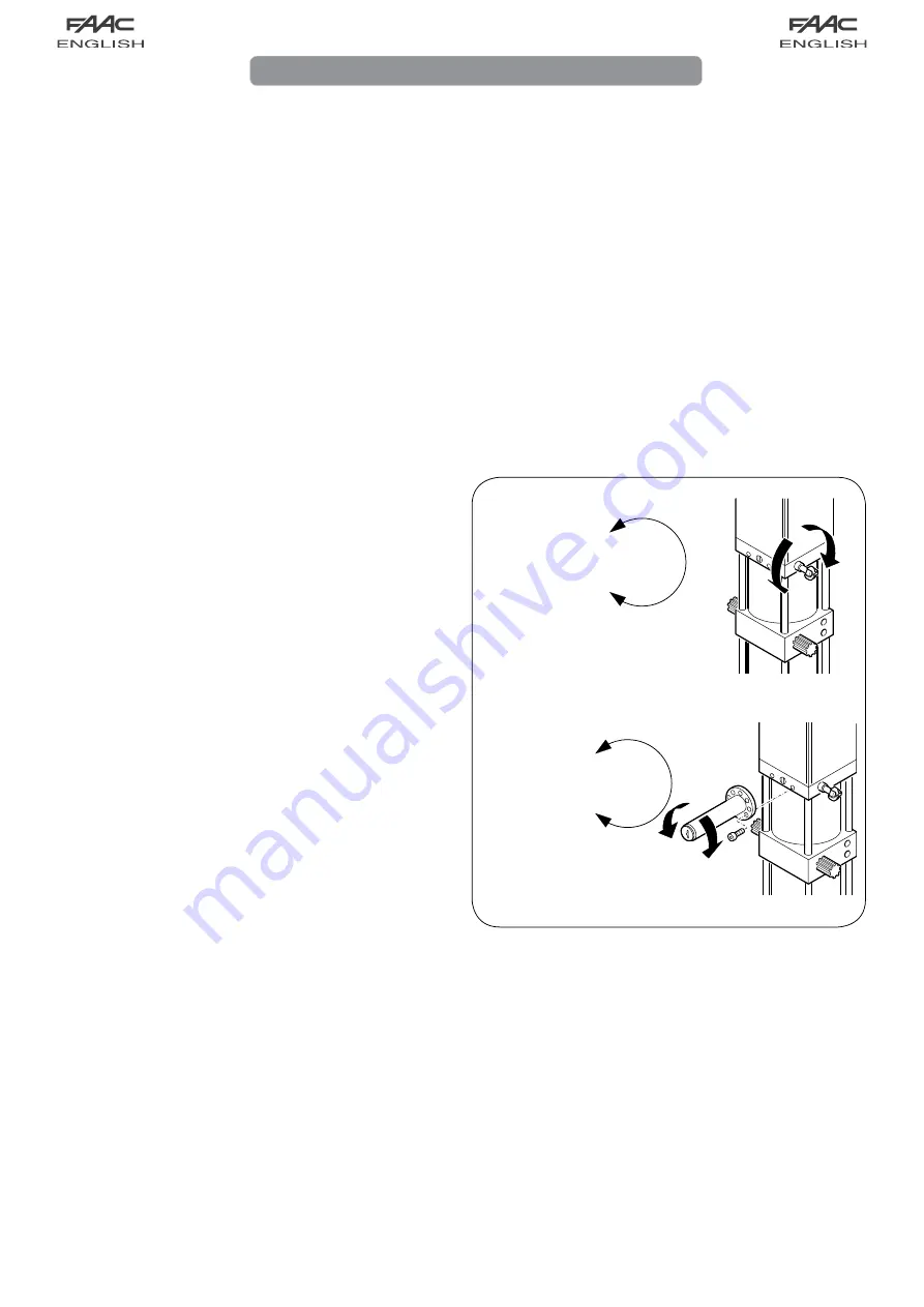
SBLOCCA/UNLOCK
DESBLOQUEAR
DEBLOQUE/ENTRIEGELT
BLOCCA/LOCK
BLOQUEAR
BLOQUE/VERRIEGELT
SBLOCCA/UNLOCK
DESBLOQUEAR
DEBLOQUE/ENTRIEGELT
BLOCCA/LOCK
BLOQUEAR
BLOQUE/VERRIEGELT
User’s guide
The automated systems may have safety devices (photocells)
which prevent the door from reclosing when an obstacle is
located in the area protected by them.
The 595 I/S automated system is fitted as standard with an
anti-crushing safety device that limits the torque transmitted to
the door.
The hydraulic system assures door locking in any position.
The door can be opened manually only after operating the
unlocking device.
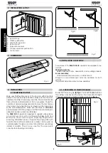
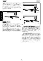
MANUAL OPERATION
If the door must be operated manually because of a power
failure or malfunction, use the unlocking device as follows.
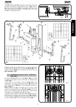
Lever release device (see Fig. 1)
External key release device (see Fig.2):
- Insert the key in the lock, and turn
the key
anticlockwise
by 1
turn.
GENERAL SAFETY REGULATIONS
If correctly installed and operated, the 595 I/S automated system
ensures a high level of safety.
However, some simple rules should be followed to avoid
accidents:
- Do not pass underneath the door while it is moving: wait until it
is completely raised.
- Do not remain stationary under the door.
- Do not stand in the vicinity of the automated system or allow
anyone else, especially children, to do so, and do not place
objects in the vicinity of the automated system. This is particularly
important during operation.
- Keep radio controls or any other pulse generator out of the
reach of children, to prevent them from accidentally operating
the automated system.
- Do not allow children to play with the automated system.
- Do not deliberately obstruct the movement of the door.
- Do not attempt to operate the door manually without first
unlocking it.
- In the event of a malfunction, unlock the door to allow access
and call a qualified technician for service.
- After manual operation, disconnect the electrical power supply
from the system before returning to normal operation.
- Do not make any modifications to components belonging to
the automated system.
- Do not attempt to perform any repair work or tamper with the
automated system. Call qualified personnel for repairs.
- At least once every six months, have the automated system,
the safety devices and the earth connection checked by a
qualified technician.
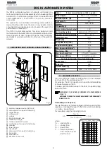
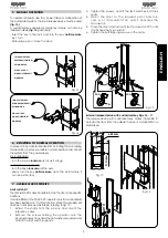
DESCRIPTION
The 595 I/S automated system is an operator for counterbalanced
up-and-over doors. It is ideal for controlling vehicle access areas
up to 5 metres wide (application with double operator) and with
medium transit frequencies.
Door operation is controlled by an electronic control unit mounted
in an enclosure which assures adequate protection against
atmospheric agents and can be fitted inside the garage.
The normal position of the door is closed in a vertical position.
When the electronic control unit receives an opening command
from the radio control or any other pulse generator, it activates
the hydraulic system and causes the door to rotate upwards by
90° to the horizontal position, thereby allowing access.
If automatic operation has been selected, the door closes
automatically after the selected pause time.
If semiautomatic operation has been selected, a second impulse
must be sent to close the door.
An open command given while the door is closing causes the
door to reverse direction of movement.
A stop command (if available) stops movement at any time.
For detailed information on door operation in the various
operating modes, contact the installation technician.
- Manually open or close the door.
RETURNING TO NORMAL OPERATION
To prevent an accidental impulse from activating the door during
this operation, before you restore normal operation, disconnect
the system from the power supply.
Lever release device (see Fig. 1).
External key release device (see Fig.2):
- turn the key
clockwise
until it stops.
- turn the key
anticlockwise
very slowly to the point where it can
be extracted.
595 I/S AUTOMATED SYSTEM
Fig. 1
Fig. 2
Summary of Contents for 595
Page 1: ...595...


