

3
10
20
30
40
50
60
70
80
90
100
0
1
2
3
4
5
6
7
8
9
10
10 11 12
Percentuale
di lav. %
Tiempo (h)
% Duty cycle
% Fréquence
d'utilisation
% Benutzungs-
frequenz
% Frecuencia
de utilización
Zeit (Std.)
Temps (h)
Time (h)
Tempo (h)
ENGLISH
595 I/S AUTOMATED SYSTEM
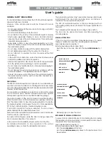
DESCRIPTION AND TECHNICAL CHARACTERISTICS
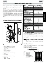
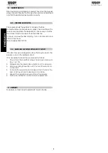
. MAXIMUM USE CURVE
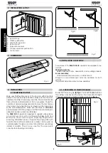
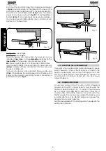
The 595 I/S automated system is a hydraulic unit formed of a
motor pump and a piston-rack assembly, which ensures optimal
automation of up-and-over garage doors for residential and
condo applications.
It is mounted on the door by means of
accessories.
The system has an adjustable anti-crushing safety system, a
device that stops and locks the door in any position, and a
convenient manual release device to be used in the event of a
power failure or malfunction.
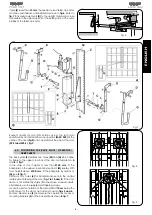
The 595 I/S automated system has been designed and
manufactured for the automation of counterbalanced up-and-over
doors. Figures A, B and C page 4 show the most commonly
used types of up-and-over doors. No other use of the system is
allowed.
1
2
4
3
5
6
7
8
9
10
11 12
13
14
15
16
a
external release device (optional)
b
side support for operator fastening
c
upper flange
d
oil filler plug
e
oil tank
f
internal release knob
g
distribution flange
h
torque adjustment screws
i
central body for operator fastening
j
cylinder
k
lower flange
l
drive shaft
m
side support for operator fastening
n
backplate
o
bleed screw
p
596 MPS control unit
Fig. 1
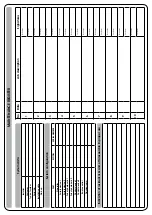
Table 1
Technical specifications of 595 I operator
Power supply
230V
~
(+6 -10 %) 50Hz
Absorbed power (W)
220
Duty cycle %
50
Oil type
FAAC HP OIL
Oil quantity (l)
1
Motor winding thermal cutout
120°
Anti-crushing system
bypass valves fitted as std
Operating ambient temperature
-20 ÷ +55 °C
Protection class
IP 31
Weight (Kg)
10
Pump flow rate (l/min.)
0.75
Angular velocity (rpm)
1.54
Max. door weight (Kg/m
2
)
15
Max torque (Nm)
400
Max. door height (m)
2.70
with 1 operator
Max. door width (m)
3.5
with 1 operator
Technical characteristics of electric motor
Speed (rpm)
1400
Power (W)
200
Current drawn (A)
1.2
Power supply
230V~ (+6 -10 %) 50Hz
The curve allows the maximum working time (T) to be obtained
as a function of the use frequency (F).
For example, the 595 I/S operators can operate uninterruptedly
at an use frequency of 50%.
To ensure good operation, keep to the field of operation lying
below the curve.
IMPORTANT: THE CURVE IS OBTAINED AT A TEMPERATURE
OF 24 °C.
EXPOSURE TO DIRECT SUN RAYS MAY REDUCE USE FREQUENCY
DOWN TO 20%.
Calculating use frequency
The use frequency is the percentage of effective working time
(o closing) with respect to the total cycle time (opening
+ c pause times).
It is calculated using the following formula:
where:
Ta = opening time
Tc = closing time
Tp = pause time
Ti = interval between
one complete cycle
and the next.
Ta + Tc
%F =
X 100
Ta + Tc + Tp + Ti
Summary of Contents for 595
Page 1: ...595...


