
4
10
c
m
A
B
S
ENGLISH
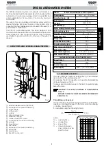
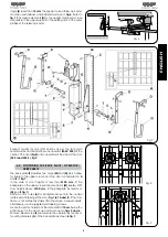
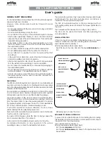
2 INSTALLATION LAYOUT
a
junction box
b
T15MP pushbutton
c
FAAC 595 I operator
d
Rx photocell
e
plus radio receiver
f
T10 key-operated pushbutton
g
Tx photocell
Fig. 2
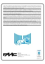
3 DIMENSIONS
Fig. 3
4 INSTALLATION
4. PRELIMINARY CHECKS
Make sure that the dimensions of the door are within the limits
stated in the technical specifications. Make sure that the door
operates smoothly. If necessary, clean the tracks and lubricate
them with a silicon based lubricant. Do not use grease. Check the
condition of all door bearings and joints. Remove the mechanical
door locks so that when the door is closed it will be locked only
by the automated system. Make sure that there is a
230 Vac
power supply point in the garage, and that it is protected by an
adequate residual current circuit-breaker.
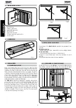
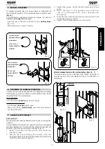
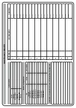
The
FAAC 595 I
operator is designed to operate various types
of up-and-over doors with counterweights.
Figs. A
,
B
, and
C
show the most common types: projecting single panel,
projecting articulated panel, non-projecting single panel with
horizontal tracks. Either metal blocks or bricks can be used as
counterweights, though some door manufacturers use springs
instead of weights. Check in any case that the door pivots
correctly when opening and closing.
Fig.B
Fig.C
Fig.A
4.2 INSTALLATION OF OPERATOR
Accessories of the
FAAC 595 I/S
operators are supplied in two
versions:
Welded assembly
- welded telescopic arms, drive shafts, and mounting brackets.
Screw assembly
- all accessories feature screw-on attachment.
Straight or curved telescopic arms are available for both
versions.
The present instructions refer to screw assembly.
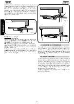
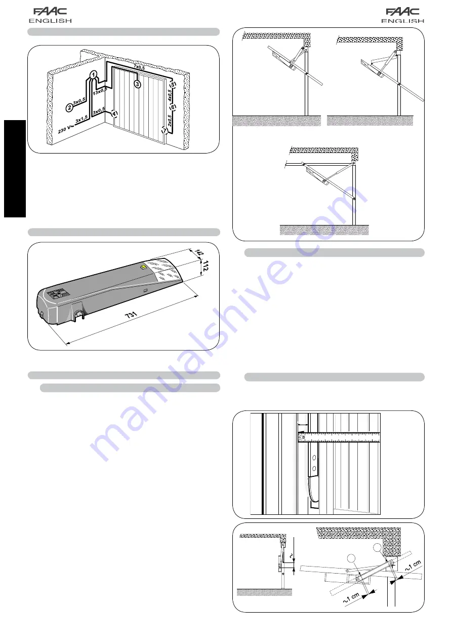
4.3. POSITIONING OF TELESCOPIC ARMS
Ensure that there is a gap
(S) fig.4
of at least
15 mm
between
the existing cross bar and the frame. This is essential if straight
telescopic arms are to rotate correctly as shown in
fig. 5
.
Fig. 4
Fig. 5
Summary of Contents for 595
Page 1: ...595...


