
5
A
B
10
c
m
ENGLISH
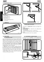
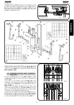
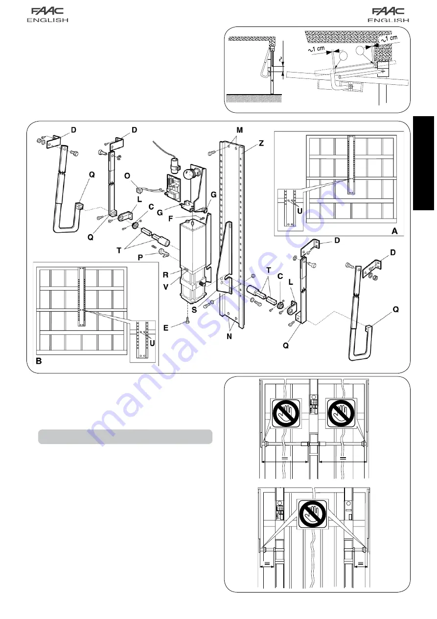
If gap
(S)
is less than
15 mm
, the special curved telescopic arms
must be used instead, and installed as shown in
fig.6
. Refer to
fig.7
to fix square elements
(D)
to the upright member as close
as possible to the upper support of the existing arm. Fit the outer
profiles of the telescopic arms.
Fig. 6
Fig.7
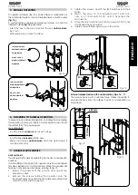
Respect maximum door dimensions as per the technical
specifications and install either one operator
(FAAC 595)
at the
centre of the door
(fig.8)
or two operators at the sides of the door
(595 I and 595 S)
,
fig.9.
Fig. 9
Fig. 8
4.4. POSITIONING THE BACK PLATE / OPERATOR /
DRIVE SHAFTS
The back plate
(Z)
features two holes
(M)
and
(N)
which allow
for fixture to the upper cross bar of the door as indicated in
A
and
B
of
fig.7
.
In the case of door heights of less than
2100 mm
, fit the
backplate on the upper cross bar by means of
(M)
(see
A
). With
door heights above
2100 mm
, fit the backplate by means of
(N)
(see
B
,
fig.7
).
Drill two 6 mm holes
(U)
for backplate fixture onto the central
reinforcement ribbing of the door (
fig.7 ref. A and B
). If the door
frame is not sufficiently sturdy (thin sheet) use screwed inserts.
Alternatively, use the supplied self-tapping screws.
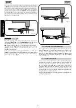
Locate the point of rotation of the drive shaft at
10 cm
below the
bottom pivot of the door’s own arm as shown in
figs. 5 and 6
.
Remove bleed screw
(F)
and secure the operator by means of
mounting brackets
(S)
on the backplate as shown
in fig.7.
Summary of Contents for 595
Page 1: ...595...


