background image

6

- 5°

T

L

ENGLISH

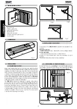
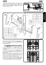
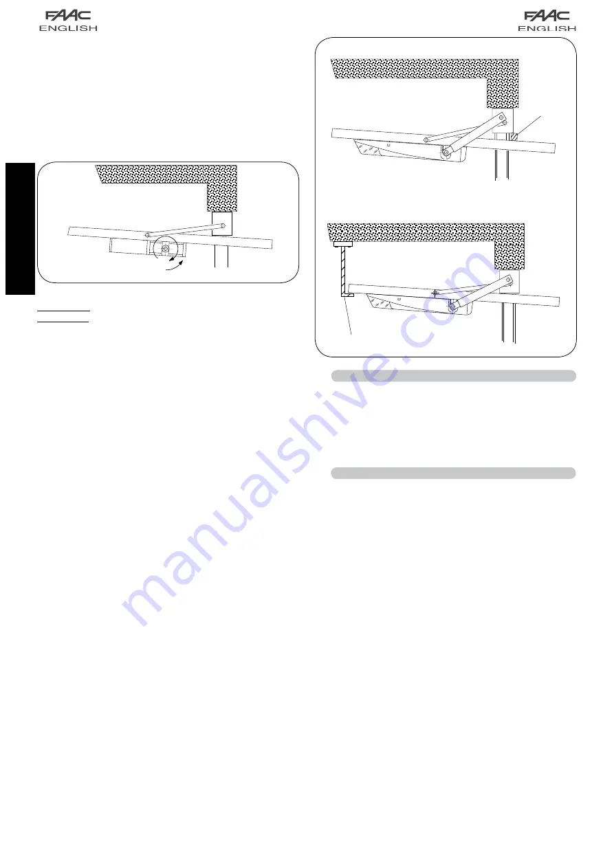
Disconnect the operator and open the garage door as indicated 
in 

fig.10

 and turn the pinion in the direction of the arrow to the 

piston limit. Rotate though approx. 

 in the opposite direction.

Close  the  door  and  fit  drive  shafts 

(T)  fig.7

  over  the  operator 

pinions and cut to size as shown in 

figs. 8/9

. Fit bushings 

(C)

 and 

brackets 

(L)


fig. 7 

on the drive shafts and secure brackets 

(L)

 on 

the door reinforcement ribbing taking care to maintain correct 
alignment of the drive shafts.
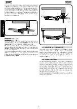
Fig. 10

Straight arm

: refer to

 fig. 5

Curved arm

: refer to 

fig. 6.

Open  the  garage  door  and  position  the  telescopic  arm  as 
indicated in 

figs. 5 or 6

. Cut the 

outer profile 

at point 

A

. Cut the 

inner profile

 of the telescopic arm at reference point 

B

.

N.B.

 Leave a gap of about 1 cm at the ends of both profiles.

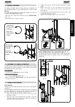
Insert the drive shafts 

(T)

 in the inner profile of the telescopic arm 

(Q) fig.7,

 already cut to size, and drill an 8 mm hole. Secure by 

means of an MA8 bolt.
To ensure smooth door closing operation install a cushion pad 

(T) fig.11. 

Alternatively, to prevent garage door off-balance and 

ensure  optimal  operator  functioning,  construct  and  install  an  

L

 bracket as shown in 

fig.12

.

Fig. 12

Fig. 11

4.5.  ADJUSTING THE COUNTERWEIGHTS

The weight of the counterweights must be increased to ensure 
smooth  operation.  If  there  is  insufficient  space  to  add  to  the 
existing counterweights, remove them and replace them with 
blocks  of  a  higher  specific  weight.  Release  the  operator  and 
move  the  door  to  half-open  position  (45°).  The  door  should 
remain in balance.

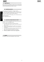
4.6.  DOUBLE APPLICATION

For up-and-over doors 3.50 to 5 m wide, one 595 I (integrated) 
operator  and  one  595  S  (slave)  operator  must  be  used.  The 
maximum  permitted  height  is  3  m.  Install  in  the  same  way 
as  for  a  single  motor 

(fig.  9)

.  The  electrical  connection  of 

the SLAVE drive unit must be made on the control unit of the  
MASTER operator. Connect the power cables of the SLAVE operator  
in parallel with those of the MASTER, taking care to respect the 
assignments and rotation direction.
Add the one supplied with the SLAVE operator in parallel with the 
existing thrust capacitor.

Summary of Contents for 595

Page 1: ...595...

Page 2: ...ION 4 4 1 PRELIMINARY CHECKS 4 4 2 INSTALLATION OF OPERATOR 4 4 3 POSITIONING OF TELESCOPIC ARMS 4 4 4 POSITIONING THE BACK PLATE OPERATOR DRIVE SHAFTS 5 4 5 ADJUSTING THE COUNTERWEIGHTS 6 4 6 DOUBLE...

Page 3: ...r to offer the utmost safety 9 FAACcannotbeheldresponsibleforfailuretoobservetechnical standards in the construction of gates and doors or for any deformation of the gates which may occur during use 1...

Page 4: ...g j cylinder k lower flange l drive shaft m side support for operator fastening n backplate o bleed screw p 596 MPS control unit Fig 1 Table 1 Technical specifications of 595 I operator Power supply 2...

Page 5: ...designed to operate various types of up and over doors with counterweights Figs A B and C show the most common types projecting single panel projecting articulated panel non projecting single panel w...

Page 6: ...k plate Z features two holes M and N which allow for fixture to the upper cross bar of the door as indicated in A and B of fig 7 In the case of door heights of less than 2100 mm fit the backplate on t...

Page 7: ...ensure smooth door closing operation install a cushion pad T fig 11 Alternatively to prevent garage door off balance and ensure optimal operator functioning construct and install an L bracket as show...

Page 8: ...e key anticlockwise up to the point where it can be extracted 7 AVAILABLE ACCESSORIES Limit switch kit The limit switch kit makes it possible to stop the door in two specific positions It can be fitte...

Page 9: ...to the correct level Use exclusively FAAC HP OIL 8 2 BLEEDING AIR FROM HYDRAULIC CIRCUIT If the door moves in an irregular manner this may be due to the presence of air in the hydraulic circuit If it...

Page 10: ...peration disconnect the electrical power supply from the system before returning to normal operation Do not make any modifications to components belonging to the automated system Do not attempt to per...

Page 11: ...chnician Customer 9 Technician Customer 10 Technician Customer Installer Customer Type of system Serial No Installation date Start up PART MODEL SERIAL NUMBER Operator Safety device 1 Safety device 2...

Page 12: ...n in vorliegendem Handbuch sind unverbindlich FAAC beh lt sich das Recht vor ohne die wesentlichen Eigenschaften dieses Ger tes zu ver ndern und ohne Verbindlichkeiten in Bezug auf die Neufassung der...

Reviews: