
7
SBLOCCA/UNLOCK
DESBLOQUEAR
DEBLOQUE/ENTRIEGELT
BLOCCA/LOCK
BLOQUEAR
BLOQUE/VERRIEGELT
SBLOCCA/UNLOCK
DESBLOQUEAR
DEBLOQUE/ENTRIEGELT
BLOCCA/LOCK
BLOQUEAR
BLOQUE/VERRIEGELT
FCC
B
FCA
A
1
1
0
m
m
ø 25 mm
N
ENGLISH
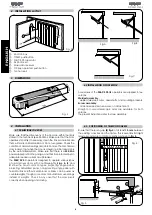
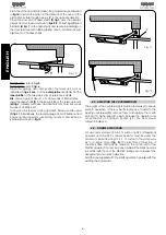
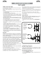
5 MANUAL OPERATION
To operate manually due to a power failure or malfunction of
the automated system, the knob release device must be used
(fig. 13)
.
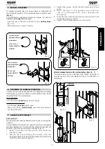
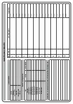
A customised key-operated emergency release can also be
installed outside
(fig. 14)
(optional)
.
- Insert the key in the lock, and turn the key
anticlockwise
by 1 turn.
- Manually open or close the door.
Fig. 13
Fig. 14
6. RETURNING TO NORMAL OPERATION
To prevent an accidental impulse from actuating the door during
this operation, before you restore normal operation, disconnect
the system from the power supply.
knob (standard):
- turn the knob
clockwise
as far as it will go.
customised key (optional):
- turn the key
clockwise
all the way;
- slowly turn the key
anticlockwise
up to the point where it
can be extracted.
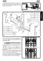
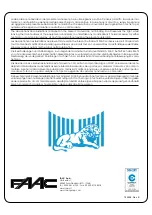
7. AVAILABLE ACCESSORIES
Limit switch kit
The limit switch kit makes it possible to stop the door in two specific
positions.
It can be fitted on the FAAC 595 I operator only if a control board
has been installed on it for this function. When this requirement
has been met, proceed as follows, referring to fig. 15:
1. Extract the shafts from the pinions, and mount the
reference cams.
2. Remove the screws holding the operator onto the
longitudinal sections, add the flat washers provided and
mount the limit switch supports.
3. Tighten the screws, and fit the limit switches into their
seats.
4. Open the door to the required point and turn
cam A of microswitch FCA until it activates the
microswitch.
5. Close the door and turn cam B of microswitch FCC until
it activates the microswitch.
6. Tighten the self-tapping screws on the cams.
Fig. 15
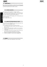
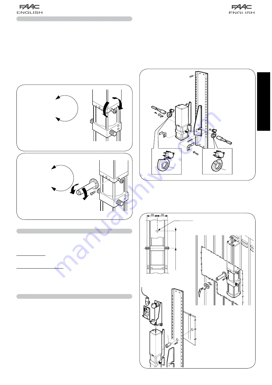
External release device with customised key Figs. 16 - 17
The release device with customised key makes it possible to
actuate the door from the outside in case of a malfunction or
breakdown.
Fig. 17
Fig. 16
Summary of Contents for 595
Page 1: ...595...


