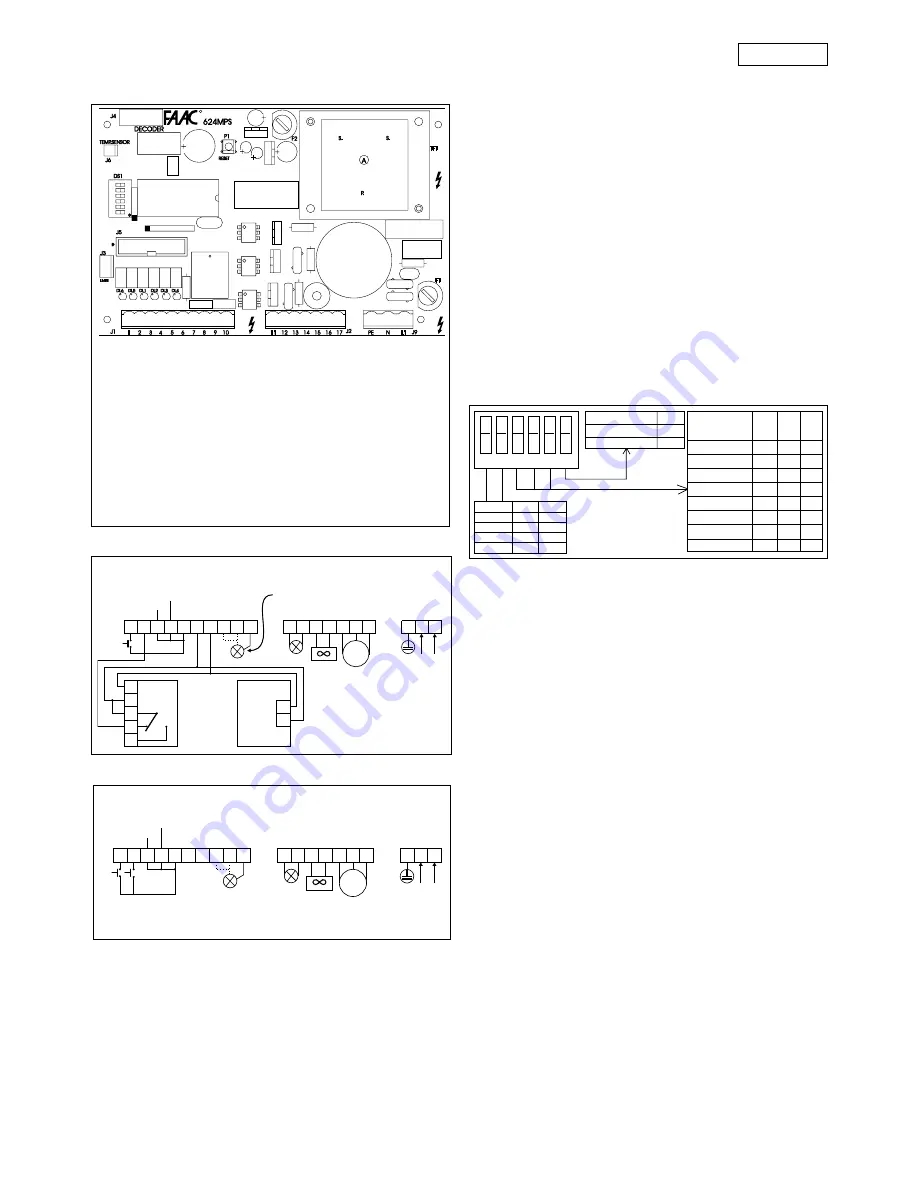
background image

17

ENGLISH

R

Fig. 13

TF1

TRANSFORMER.

J1

REMOVABLE LOW-VOLTAGE TERMINAL
STRIP

J2

REMOVABLE POWER TERMINAL STRIP

J3

LIMIT SWITCH CONNECTOR

J4

DECODER CONNECTOR

J5

CONNECTOR FOR FSW, SLAVE, RELAY
BOARDS

J6

CONNECTOR FOR NTC PROBE

J9

REMOVABLE TERMINAL STRIP
NETWORK POWER SUPPLY

P1

RESET PUSHBUTTON.

F1

F5A FUSE (MOTOR).

F2

T1.6 FUSE (ACCESSORIES).

DL1

OPEN IMPULSE LED  (A/E/P LOG.)

DL2

CLOSE IMPULSE LED (P LOG.)
SAFETY CONTACT (A LOG.)

DL3

STOP IMPULSE LED

DL4

ALARM LED (PANIC)

DL5

OPENING LIMIT SWITCH LED

DL6

CLOSING LIMIT SWITCH LED

624 MPS CONTROL UNIT

A / E LOGICS CONNECTIONS

STOP

This word indicates a activating device with normally
closed contact, whose activation suspends the current
status of the beam (opening, pause or closing), until
another pulse is sent.

SAFETY

This word indicates all devices (photocells, sensitive
pneumatic safety edges, magnetic coils) with normally
closed contact, which interrupt the movement of the
beam whenever there is an obstacle within their range.

PANIC

This word indicates a activating device with normally
closed contact, which is activated in an emergency and
causes the beam to open, suspending its current status
(open) until the RESET pushbutton is pressed.

PROGRAMMING THE MICROSWITCHES

NOTE: WHENEVER YOU CHANGE THE MICROSWITCH
PROGRAMMING, PRESS THE RESET PUSHBUTTON AFTERWARDS.

(*)  IMPORTANT!:

 The R logic (remote) must be selected

only if there are two opposing barriers that work
simultaneously. (See paragraph "624 SLAVE CARD", below.)

OPERATION OF SAFETY DEVICES

In the A or E logics, it is possible to obtain two different
types of safety device operation, depending on the pause
times that are selected:
- PAUSE TIMES WITH LAMP PRE-FLASHING (10-20-30-40 sec):

the closing movement is stopped, then reversed on
disengagement.

- PAUSE TIMES WITHOUT LAMP PRE-FLASHING:(0-5-10-20 sec):

the closing movement is reversed at once.

ALARM CONDITION

It arises in the following cases:
1)

Enabling of anti-panic input.

2)

Activation of safety TIME-OUT device, which interrupts
the operation of the system when operating time
exceeds 30 sec.

3)

Simultaneous triggering of the two limit switches.

4)

Microprocessor reading anomaly (syncro).
The alarm condition is indicated by the quick flashing
(0.25 sec) of the Warning Light LED and of the warning
light (if connected).
In this condition, all the functions of the system are
disabled. Normal operation is restored only after the
cause of the alarm has been eliminated and the RESET
pushbutton has been pressed.

Fig. 14

1 2 3 4 5 6 7 8 9 10

111213 14 15 16 17

PE N L1

3

4

5

1

2

1

2

M

OPEN

NC

FX

NA

FX

FAAC
LAMP

24 VAC
MAX 5 W

VENTOLA
FAN
VENTILATEUR
LÜFTER
VENTILADOR

MOTOR

STOP

+

+

ANTIPANICO
PANIC ALARM
ANTIPANIQUE
PANIKSCHUTZ
ANTIPÁNICO

LAMPADA SPIA
WARNING LIGHT
LAMPE TÉMOIN
KONTROLLAMPE
TESTIGO

230 VAC +6%
-10% 50-60 Hz

24 Vcc

P LOGIC CONNECTIONS

Fig. 15

1 2 3 4 5 6 7 8 9 10

111213 14 15 16 17

PE N L1

M

ANTIPANICO
PANIC ALARM
ANTIPANIQUE
PANIKSCHUTZ
ANTIPÁNICO

NC

NA

FAAC
LAMP

24 VAC
MAX 5 W

MOTOR

STOP

+

OPEN

CLOSED

VENTOLA
FAN
VENTILATEUR
LÜFTER
VENTILADOR

LAMPADA SPIA
WARNING LIGHT
LAMPE TÉMOIN
KONTROLLAMPE
TESTIGO

230 VAC +6%
-10% 50-60 Hz

24 Vcc

{

1

2

3

4

5

6

Logic

SW1

SW2

A

ON

ON

E

OFF

ON

P

ON

OFF

R(*)

OFF

OFF

Deceleration

SW6

short

OFF

long

ON

Pausetime

SW3 SW4 SW5

(sec)

Ø

OFF

OFF

OFF

5

ON

OFF

OFF

10

OFF

ON

OFF

20

ON

ON

OFF

10

OFF

OFF

ON

20

ON

OFF

ON

30

OFF

ON

ON

40

ON

ON

ON

With 5 sec pre-flashing

DESCRIPTION OF TERMINAL STRIP

OPEN

This word indicates any activating device with normally
open contact, whose activation causes the beam to perform
an opening movement. In automatic and semi-automatic
logics, it controls both opening and closing movements.

CLOSE

This word indicates any activating device with normally
open contact, whose activation causes the beam to
perform a closing movement. (Present only in P logic).

Summary of Contents for 620 STANDARD

Page 1: ...lich 100 Altpapier pour la nature papier recyclé 100 for nature recycled paper 100 per la natura carta riciclata 100 para la naturaleza 100 papel reciclado 620 640 642 624 MPS C ERME T A Z I E N D A C E R TIF I C A T A UNI EN ISO 9001 085 ...

Page 2: ...p A Bologna 20 de diciembre de 1995 Presidente Administrador Delegado KONFORMITÄTSERKLÄRUNG NACH ISO IEC NORM RICHTLINIE 22 EN 45014 HERSTELLERNAME FAAC S p A HERSTELLERANSCHRIFT FAAC S p A Via Benini 1 40069 Zola Predosa BOLOGNA ITALY Hiermit erklären wir eigenverantwortlich daß die Produkte Modelle Serie 402 422 400 750 760 746 844 820 860 590 1 593 580 595 550 500 RC 503 RC 560 630 620 640 642 ...

Page 3: ... subsequent amendments 91 368 EEC 93 44 EEC and 93 68 EEC complieswiththeessentialsafetyrequirementsinthefollowingEECDirectives 73 23 EEC and subsequent amendment 93 68 EEC 89 336 EEC and subsequent amendments 92 31 EEC and 93 68 EEC and furthermore declares that unit must not be put into service until the machinery into which it is incorporated or of which it is a component has been identified an...

Page 4: ... shall be provided for the installation with an opening distance of the contacts of 3 mm or more Alternatively use a 6A thermomagnetic breaker with multi pole switching 13 Ensure that there is a differential switch up line of the electrical system with a trip threshold of 0 03A 14 Check that the earthing plant is in perfect condition and connect it to the metallic parts Also earth the yellow green...

Page 5: ...ndcablepassagehole 19 Anchor bolt 20 Baseplate 21 Right handcablepassagehole 22 Earth connector fixing screw 23 Cablepipe 24 624 MPS electronic control unit 25 Right handconnectingpipe 26 Unlocking lever 27 Support position for 460 mm spring 28 Air intake grille 29 Right handpiston 30 Support position for400 mm spring 31 Balancespringsupport 32 Balancespring 33 Right handpistonbleedscrew 34 Therma...

Page 6: ... automation system make sure that the following requirements are met During its movement the beam does not strike against obstacles or overhead power cables The characteristics of the ground must ensure sufficient support for the foundation plinth There must be no pipes or electrical cables in the area to be dug for installing the foundation plinth If the housing is located in a vehicle transit ar...

Page 7: ...alled with the door on the premises side 2 Set up the operator for manual operation as described in section 6 Fig 8 3 Remove the two breather screws as shown in Figure 9 and keep them in a safe place 4 Assemble the beam using the screws supplied as shown in Figures 10 and 10 b Apply the cap to the hole 620 only The rubber edged side of the beam must be in the closing direction 5 Adjust the mechani...

Page 8: ...SORIES LED ON contact closed OFF contact open FCC closing limit switchnot engaged closing limit switch engaged FCA opening limit switchnot engaged opening limit switch engaged OPEN activated deactivated CLOSED FSW activated saf disengaged deactivated saf engaged STOP deactivated activated ALARM beammoving beamstationary WARN LIGHT see warn light operation see warn lightoperation POWER motor power ...

Page 9: ...ec the closing movement is reversed at once ALARM CONDITION It arises in the following cases 1 Enabling of anti panic input 2 Activation of safety TIME OUT device which interrupts the operation of the system when operating time exceeds 30 sec 3 Simultaneous triggering of the two limit switches 4 Microprocessor reading anomaly syncro The alarm condition is indicated by the quick flashing 0 25 sec o...

Page 10: ...m away from the limit switch 3 Re lock the system see paragraph 6 and carry out a few test cycles in order to check whether the positioning of the limit switches the balancing of the spring and the transmitted torque are correct 5 4 TESTING THE AUTOMATION SYSTEM Once installation is complete affix the danger warning adhesive on the top of the housing Fig 18 Carry out a thorough functional check of...

Page 11: ...EGELT BLOQUEAR SBLOCCA UNLOCK DEBLOQUE ENTRIEGELT DESBLOQUEAR BLOCCA LOCK BLOQUE VERRIEGELT BLOQUEAR SBLOCCA UNLOCK DEBLOQUE ENTRIEGELT DESBLOQUEAR Fig 19 b Fig 20 8 2 BLEEDING AIR FROM THE HYDRAULIC CIRCUIT If the beam moves in an irregular manner this may be due to the presence of air in the hydraulic circuit 1 Remove the breather screw Fig 9 2 Actuate the beam electrically while the beam is ope...

Page 12: ...e skirt kit is fitted the balance spring must be adjusted ARTICULATION KIT Fig 25 mod 620 only The articulation kit makes it possible to articulate the rigid beam to a maximum ceiling height of 3 m IMPORTANT If the articulation kit is fitted the balance spring must be adjusted END FOOT Fig 26 The end foot supports the beam in closed position and prevents it from bending downwards IMPORTANT If the ...

Page 13: ...mounted in an enclosure which assures adequate protection against atmospheric agents and can be fitted inside the housing The normal position of the beam is closed in a horizontal position When the electronic control unit receives an opening command from the remote radio control or any other control device it activates the hydraulic system and causes the beam to rotate upwards by 90 to the vertica...

Reviews: