12
ENGLISH
ENGLISH
5.
FAULT CONDITIONS
The following conditions effect normal operation of the
automation:
a
microprocessor error
b
intervention of the electronic safety timer (interruption of
operation after continuous working time exceeds 255
seconds).
c
disconnection of the limit switch cable connector
•
Conditions
a
and
b
have the sole effect of causing the
automation to stop.
•
Condition
c
(indicated by the fact that both LEDs FCA
and FCC are off) prevents the card from operating:
normal operation is only resumed after the cause of the
alarm has been eliminated and the RESET button has been
pressed (or the power supply has been momentarily inter-
rupted).
For repairs contact an authorised FAAC Repair Centre.
J4
J3
CH-DX CH-SX
J5
J6
844MPSR
+
-
LIMIT
LIMIT
J2
4
3
2
1
J1
844MPS
INTERFACE
AP
CH
CO
M
M
~
M
~
J3
J5
FINECORSA
LIMIT SWITCH
FIN DE COURSE
ENDSCHALTER
FIN DE CARRERA
BLACK
BLUE
BROWN
BLACK
BLUE
BROWN
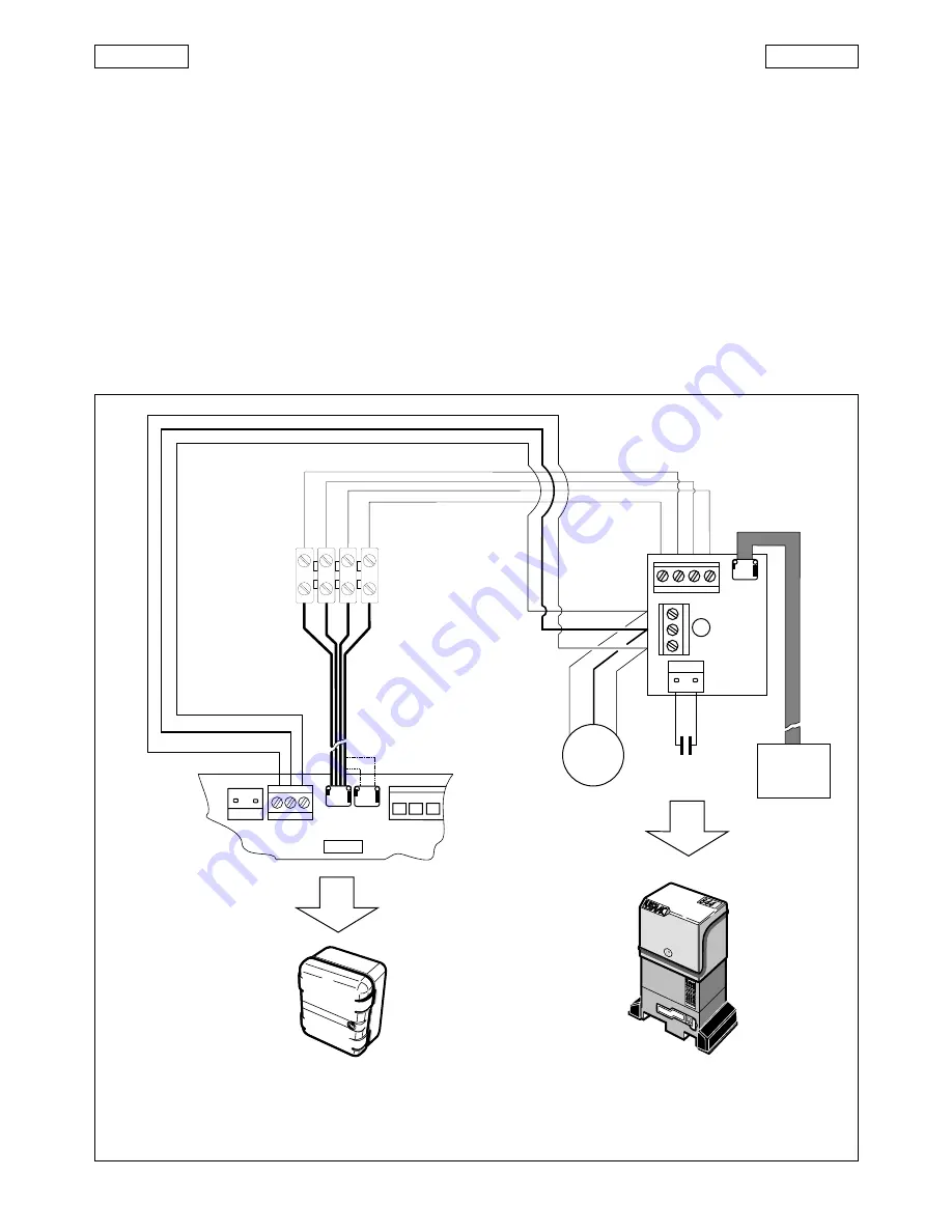
6. SEPARATE INSTALLATION
If you prefer to install the control unit 844 MPSR separately from
the operator, use the 844 INTERFACE card and the adapter
cable (provided with the geared motor) and connect them
together as shown in fig. 11.
The surge capacitor can be coupled either to the control
unit (J6) or to the interface card (J5).
Important:
make sure that the cable colour code is
respected when connecting the electric motor.
Install the control unit 844 MPSR in a box with
minimum housing protection IP55.
Fig. 11


