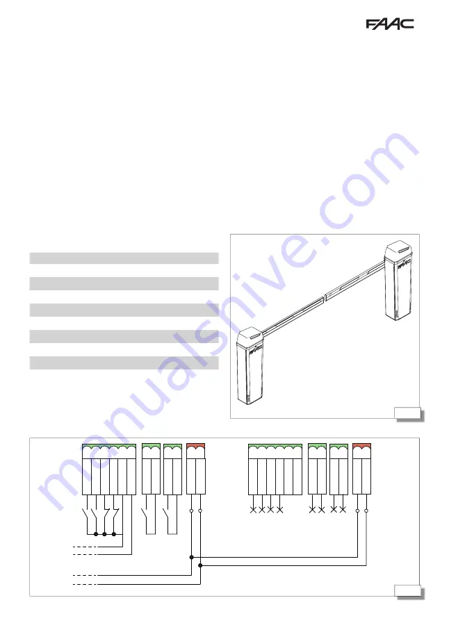
44
45
B614
47
532297 - Rev.D
OPEN
1
2
3
4
5
6
+24V
GND
EMER
ST
OP
CL
OSE
BUS
L
OOP 2
L
OOP 2
L
OOP 1
L
OOP 1
BUS
OPEN
1
2
3
4
5
6
+24V
GND
EMER
ST
OP
CL
OSE
BUS
L
OOP 2
L
OOP 2
L
OOP 1
L
OOP 1
BUS
1 2
1 2
9.
MASTER-SLAVE
(
44
) The
Master
-
Slave
configuration makes it pos-
sible to install two opposing barriers with synchronous
movement.
When programming one barrier must be defined as
Master
and the other as
Slave
. The
Master
barrier
manages all the controls and movements.
The control devices and any external loops must be
connected to the
Master
barrier.
Each barrier must be programmed on the basis of the
length and configuration of the arm. The function-
ing logic must only be programmed on the
Master
board. The anticrushing function is active on each
barrier and commands the inversion of both.
CONNECTION
1. Connect the barrier with BUS 2easy polarised
connection
45
).
2. Connect the devices (see the chapter § 5.2). The
inputs for the command devices and any external
loop are inhibited on the
Slave
board.
Connections
Master
Slave
Power supply
Motor
Encoder
Head lighting
Arm lights
Control devices
Loop
Outputs
Flashing light
3. The BUS 2easy devices can be connected to the
Master
or to the
Slave
board. The devices must be
registered on the
Master
barrier.
Summary of Contents for B614
Page 1: ...B614...


