XTR B
7
532109 - Rev.A
ON
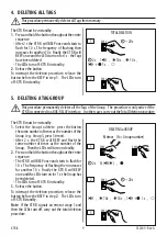
1 2 3 4 5
Dip 5 = OFF
1CH
ON
1 2 3 4 5
Dip 5 = ON
2CH
3.2 CONNECTING TO A BUS-RELAY
INTERFACE
CONFIGURING THE DIP-SWITCHES
Position the dip-switches (
3
) in order to specify:
-
1CH or 2CH mode of operation (Dip-switch 5)
-
ID device identifier (Dip-switches 1-2)
Dip-switches 3-4 are irrelevant.
!
Each control device connected to the BUS
line must have a different ID.
L
L
In order to add an XTR B to an existing
system you must know the IDs of the other
BUS 2easy devices that are present. See
the instructions for the devices already
installed in order to identify the IDs that
have already been used.
For future reference, you can make a note of
the IDs of the installed devices in the table
at the end of this manual.
ASSIGNING THE TAGS TO THE RELAYS
In single channel mode (1CH)
, each enabled Tag can
activate only one relay. The relay is assigned during
the storage phase by selecting a Group.
In two channel mode (2CH)
, each enabled Tag can
activate 2 relays (not simultaneously). The pair
of relays is assigned during the storage phase by
selecting a Group. The Tag activates one relay with
command 1 and the other with command 2 (see § 8).
CORRESPONDENCE BETWEEN GROUP/RELAY
3
ID in 1CH or 2CH mode
Dip-switch
1 2 3 4
ID
Groups available in 1CH mode
Groups available in 2CH mode
0 0 x x
ID1
1 , 2 , 3 , 4
1 , 2
0 1 x x
ID2
1 , 2 , 3 , 4
1 , 2
1 0 x x
ID3
1 , 2 , 3 , 4
1
1 1 x x
ID4
1 , 2
1
Group 1
Group 2
Group 3
Group 4
XTR B (1CH) Relay 1
XTR B (2CH)
Command 1 Relay 1
Command 2 Relay 2
XTR B (1CH) Relay 2
XTR B (2CH)
Command 1 Relay 3
Command 2 Relay 4
XTR B (1CH) Relay 4
XTR B (1CH) Relay 3
1 = ON ; 0 = OFF ; x = irrelevant
Summary of Contents for XTR B INOX
Page 1: ...XTR B EN...
Page 7: ...XTR B 05 532109 Rev A 4 5 5 click XTRBINOX XTRB...


