background image

Version 05/06 - Page 2

Venting requirements

Maximum length of ductwork

Duct length is given as a general reference only. For a longer 
duct  run,  or  smaller  duct  system,  contact  a  qualified  and 
trained duct installer.  

Check with local codes for makeup 

air requirements, if any.

    It  is  recommended  that  you  use 

round duct instead of rectangular duct, especially if elbows are 
required. If rectangular duct is required, if should be transitioned 
to 10" (25.4 cm) round duct as soon as possible.

For best performance, use no more than three 90

°

 elbows. 

If more than one elbow is used, make sure that there is a 

minimum of 24 inches of straight duct between any two 

elbows.  Do not install two elbows together.

55 feet for 10" round ductwork - count 90

°


elbows as 5 feet and  45

°

 elbows as 3 feet.

Begin the installation

1.

 Discard any cardboard packaging from the blower wheel.

2.

 Remove wiring box cover and screws.

3.

  Attach  an  appropriate  U.L./CSA-listed  strain  relief  in  the 

knockout.

Note: For most installations, it is recommended that the strain relief 
be installed so that it can be tightened from inside the remote blower 
housing.

4.

 Reattach the wiring box cover loosely.  It will be removed again 

later.

Follow  the  instructions  on  the  next 

page for your type of installation

Determine which ducting method is best for your application. 
Duct system can extend either through the wall or the roof.  
Locate the remote blower so that the length of the duct system 
and the number of elbows is kept to a minimum to provide 
efficient performance. Where possible, remote blower should 
be centered between wall studs or roof rafters. The size of the 
duct system should be uniform. 

Do not install two elbows 

together. 

Use duct tape to seal all joints in the duct system. Use caulking to 
seal remote wall or floor opening around the cap.  

Flexible duct 

is not recommended.

 It creates back pressure/air turbulence 

and greatly reduces performance.  Make sure there is proper 
clearance within the wall or floor for exhaust duct before making 
cutouts. Avoid pipes, wires, or other duct systems that may 
be running through the wall. Do not cut a joist or stud unless 
absolutely  necessary.  If  a  joist  or  stud  must  be  cut,  then  a 
supporting frame must be constructed. 

The remote blower carton contains a duct collar plate.

• The duct collar plate attaches to the front of downdraft duct 
system plenums so that the 10" (25.4 cm) round duct can be 
attached to the downdraft duct system.

Make sure that there is enough space for any vent transitions that 
may be needed between the remote blower and the connecting 
vent system.  For optimum performance, locate any necessary 
vent transitions nearest to the rangehood or downdraft that will 
be used with this power system. This remote blower requires 
a separate U.L./CSA approved wiring cable that
should be installed at the same time the vent system is being 
installed.

Install this side of the fan 

facing an unoccupied space.

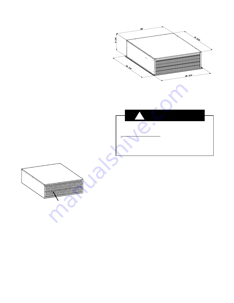
Dimensional diagram

You can be killed or seriously injured if you don’t follow 
instructions.
Excessive Weight Hazard
Use  two  or  more  people  to  move  and  install  remote 
blower.
Failure to do so can result in back or other injury.

   WARNING

MAKE  SURE  THAT  THE  DISCHARGE  END  OF  THE  REMOTE 

BLOWER FACES AWAY FROM THE DIRECTION OF PREVAILING 

WINDS.

!

Summary of Contents for 1200 CFM

Page 1: ...le Wire sizes must conform to the requirements of the National Electrical CodeANSI NFPA70 latestedition orCanadianElectricalCode C22 1 and C22 2 No 113 M1984 or latest edition and all local codes and ordinances 14 gauge wire minimum is recommended Remote Blower 1200 CFM Installation Instructions Use Care Manual You can be killed or seriously injured if you don t follow instructions TO REDUCE THE R...

Page 2: ...performance Where possible remote blower should be centered between wall studs or roof rafters The size of the duct system should be uniform Do not install two elbows together Useducttapetosealalljointsintheductsystem Usecaulkingto sealremotewallorflooropeningaroundthecap Flexibleduct is not recommended It creates back pressure air turbulence and greatly reduces performance Make sure there is prope...

Page 3: ...r slope of roof that minimizes vent run Avoid obstacles such as TV leads electric lines etc If remote blower top is level with roof peak it will not be seen from street Remember this location as you work from inside the attic 2 Mark a point half way between the rafters and drill a guide hole at this point 3 From the outside using the guide hole as a starting point mark the rectangular cut out as i...

Page 4: ... 9 cm dia hole between rafters 2 Build a sloping base that will mount the remote blower at a minimum pitch of 2 1 2 6 4 cm 3 Weatherproof the base as required 4 Locatethebasesothattheremoteblower sventalignswiththe 11 27 9cm dia holeandtheblowersitsevenlyonthebasewith no gaps Note Make sure that the discharge end of the remote blower faces away from the direction of prevailing winds 5 Usedimension...

Page 5: ...le bas ou la hotte Utiliser du câble flexible blindé ou à gaine non métallique Un serre câble homologation UL CSA doit être installé à chaque extrémité du câble d alimentation La taille des conducteurs doit satisfaire les prescriptions de la plus récente édition du Code national de l électricité ANSI NFPA 70 ou des normes CSA C22 1 94 Code canadien de l électricité C22 1 et C22 2 N 0 113 MI984 ou l...

Page 6: ... placer tout raccord de transition nécessaire aussi près que possible de la hotte ou du système d aspiration par le bas utilisé e en conjonction avec ce ventilateur Ce ventilateur extérieur devra être alimenté par un câble électrique homologation UL CSA indépendant installé en même temps que le circuit d évacuation Longueur maximale du circuit d évacuation 55 pi pour Dia 10 po conduit d évacuation...

Page 7: ...r un endroit sur le versant arrière du toit qui minimisera la longueur du conduit d évacuation Éviter tout obstacle comme câble de télévision conducteur électrique etc Si le sommet du ventilateur extérieur est au même niveau que le faîte du toit il ne sera pas visible depuis la rue tenir compte de ceci lors des opérations effectuées dans le grenier 2 Marquer un point centré entre les solives pour ...

Page 8: ... Respecter les dimensions mentionnées à la FIGURE 1 ou 2 à la page 3 pour positionner le trou de 3 cm 1 1 4 po pour le passage du câblage diagramme de câblage Figure 3 sur un toit plat Pour l installation du ventilateur extérieur sur un toit plat Risque possible de décès ou de blessure grave si vous ne suivez pas le instructions AVERTISSEMENT POUR MINIMISER LES RISQUES D INCENDIE CHOC ÉLECTRIQUE O...

Reviews: