background image


ES 

5

55 

SALIDA DEL AIRE VERSIÓN FILTRANTE 

•  Realizar un orificio de ø 125 mm en la repisa de encima de la 

campana. 

•  Introducir la brida de reducción 

9

 en la salida del cuerpo de la 

campana. 

•  Conectar la salida del cuerpo de la campana con la parte supe-

rior del mueble colgante mediante un tubo rígido o flexible de 
ø120 mm, a discreción del instalador. 

•  Fijar el tubo con abrazaderas adecuadas. Este material no se 

proporciona en dotación. 

•  Fijar la rejilla de dirección 

8

 en la salida del aire reciclado me-

diante los 2 tornillos 

12e

 (2,9 x 9,5) en dotación. 

•  Controlar que estén presentes los Filtros Antiolor al Carbón 

activo. 


9

ø 125

8

12e

CONEXIÓN ELÉCTRICA 

•  Conectar la campana a la red de alimentación eléctrica insta-

lando un interruptor bipolar con apertura de los contactos de 3 
mm como mínimo. 

•  Quitar los Filtros antigrasa y asegurase de que el conector del 

Cable de acometida esté colocado correctamente en el enchufe 
del Aspirador. 


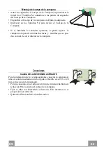
Montaje de la chimenea 

Chimenea superior 

•  Ensanchar ligeramente las dos faldas laterales, engancharlas 

detrás de las bridas 

7.2.1

 cerrarlas hasta el tope. 

•  Fijar a los lados de las bridas con los 4 tornillos 

12c

 en dota-

ción. 

Chimenea inferior 

•  Enganchar las lengüetas situadas en la parte inferior de la chi-

menea en las sedes correspondientes situadas en el cuerpo de la 
campana. 

•  Sujetar lateralmente la parte inferior al Cuerpo de la Campana, 

con dos tornillos 

12c 

incluidos en la dotación. 


2.1

7.2.1

12c

2.2

Summary of Contents for 320.0538.968

Page 1: ...Libretto di Istruzioni Instructions Manual Manuel d Instructions Bedienungsanleitung Gebruiksaanwijzing Manual de instrucciones Kullanim Kilavuzu Instrukcja Obs ugi...

Page 2: ...ONSIGNES DE S CURIT 22 CARACTERISTIQUES 25 INSTALLATION 26 UTILISATION 29 ENTRETIEN 30 INHALTSVERZEICHNIS SICHERHEITSINFORMATIONEN 31 CHARAKTERISTIKEN 34 MONTAGE 35 BEDIENUNG 38 WARTUNG 39 INHOUDSOPGA...

Page 3: ...ERIKLER G VENL K HAKKINDA B LG LER 76 ZELLIKLER 79 MONTAJ 80 KULLANIM 83 BAKIM 84 85 88 89 92 93 SPIS TRE CI INFORMACJE DOTYCZ CE BEZPIECZE STWA 94 W A CIWO CI TECHNICZNE 97 INSTALACJA 98 U YTKOWANIE...

Page 4: ...lati a un altezza inferiore vedere il paragrafo relativo alle dimensioni di lavoro e all installazione Se le istruzioni di installazione del piano cottura a gas specificano una distanza maggiore di qu...

Page 5: ...r lo scarico dei fumi importante attenersi scrupolosamente ai regolamenti stabiliti dalle autorit locali AVVERTENZA prima di installare la cappa rimuovere le pellicole di protezione Usare solo viti e...

Page 6: ...zzano gas o altri combustibili non applicabile ad apparecchi che scaricano unicamente l aria nel locale Il simbolo sul prodotto o sulla sua confezione indica che il prodotto non pu essere smaltito com...

Page 7: ...opico formato da 2 1 1 Camino Superiore 2 2 1 Camino Inferiore 8 1 Griglia direzionata 9 1 Flangia di riduzione 150 120 mm Rif Q t Componenti di Installazione 7 1 1 Staffe Fissaggio Corpo Cappa 7 2 1...

Page 8: ...dal limite superiore e a 324 mm dall angolo della parete Segnare i centri dei Fori della Staffa Appoggiare come indicato una Staffa 7 2 1 a X mm sotto la prima staffa X altezza Cami no Superiore in d...

Page 9: ...per mezzo di altre viti con tassello posizionabili dall interno del corpo cappa Vr Connessioni USCITA ARIA VERSIONE ASPIRANTE Per installazione in Versione Aspirante collegare la Cappa alla tubazione...

Page 10: ...CONNESSIONE ELETTRICA Collegare la Cappa all Alimentazione di Rete interponendo un Interruttore bipolare con apertura dei contatti di almeno 3 mm Rimuovere i Filtri antigrasso vedi par Manutenzione e...

Page 11: ...ima adatta ad un ricambio d aria continuo particolarmente silenzioso in presenza di pochi vapori di cottura V2 Velocit Velocit media adatta alla maggior parte delle condizioni d uso dato l ottimo rapp...

Page 12: ...ima di rimontarli Rimontarli facendo attenzione a mantenere la maniglia verso la parte visibile esterna Filtri antiodore al Carbone attivo Versione Filtrante Il Filtro antiodore al Carbone attivo non...

Page 13: ...height please refer to the paragraphs on working dimensions and installation If the instructions for installation of the gas hob specify a greater distance this must be respected Check that the mains...

Page 14: ...to be adopted for fume discharging it is important to closely follow the regulations pro vided by the local authorities WARNING Before installing the Hood remove the protective films Use only screws a...

Page 15: ...ls not applicable to appliances that only discharge the air back into the room The symbol on the product or on its packaging indicates that this product may not be treated as household waste Instead i...

Page 16: ...Chimney comprising 2 1 1 Upper Section 2 2 1 Lower Section 8 1 Directional grid 9 1 Reducer Flange 150 120 mm Ref Q ty Installation Components 7 1 1 Hood Connector Support 7 2 1 4 Upper Chimney Sectio...

Page 17: ...f the wall Mark the wall at the centres of the holes in the bracket Place bracket 7 2 1 on the wall as shown at X mm below the first bracket X height of the upper chimney section supplied and 324 mm f...

Page 18: ...o the wall using two more screws with wall plugs which can be positioned from inside the hood canopy Vr Connections DUCTED VERSION AIR EXHAUST SYSTEM When installing the ducted version connect the hoo...

Page 19: ...CONNECTION Connect the hood to the mains through a two pole switch hav ing a contact gap of at least 3 mm Remove the grease filters see paragraph Maintenance being sure that the connector of the feedi...

Page 20: ...on and off at low speed Used to provide a continuous and silent air change in the presence of light cooking vapours V2 Speed Medium speed suitable for most operating conditions given the optimum trea...

Page 21: ...to dry before refitting When refitting the filters make sure that the handle is visible on the outside Activated charcoal filter Recirculation version These filters are not washable and cannot be rege...

Page 22: ...inf rieure voir le paragraphe concernant les dimensions de travail et l installation Si les instructions d installation du plan de cuisson gaz sp cifient une distance sup rieure celle indiqu e ci des...

Page 23: ...par les autorit s locales AVERTISSEMENT Avant d installer la hotte retirer les films de protection Utilisez exclusivement des vis et des petites fournitures du type adapt pour la hotte AVERTISSEMENT t...

Page 24: ...temps que des appareils utilisant du gaz ou d autres combustibles non applicable aux appareils qui vacuent l air uniquement dans la pi ce Le symbole marqu sur le produit ou sur son emballage indique...

Page 25: ...lescopique form e de 2 1 1 Chemin e Sup rieure 2 2 1 Chemin e Inf rieure 8 1 Grille 9 1 Flasque de R duction 150 120 mm R f Q t Composants pour l installation 7 1 1 Support de Fixation de la Hotte 7 2...

Page 26: ...ou la limite sup rieure et 324 mm de l angle de la paroi Marquer les centres des trous rainur s de la bride Poser comme indiqu la bride 7 2 1 X mm sous la premi re bride X hauteur chemin e sup rieure...

Page 27: ...s vis avec cheville qui peuvent tre mises en place depuis l int rieur du corps de la hotte Vr Branchements SORTIE AIR VERSION ASPIRANTE Pour l installation en version aspirante relier la hotte au tube...

Page 28: ...BRANCHEMENT ELECTRIQUE Brancher la hotte sur le secteur en interposant un interrupteur bipolaire avec ouverture des contacts d au moins 3 mm Enlever les filtres graisse voir Entretien et s assurer qu...

Page 29: ...esse minimale pour un rechange d air permantent particuli rement silencieux en cas de faibles va peurs de cuisson V2 Vitesse Vitesse moyenne pour la plupart des conditions d utilisation tant donn le r...

Page 30: ...e les remonter Remonter les filtres en veillant ce que la poign e reste vers la partie visible externe Filtre anti odeur Version filtrante Il ne sont pas lavables ni r g n rables il faut les remplacer...

Page 31: ...ge Modelle k nnen auch niedriger installiert werden siehe Absatz Installation Sollten die Installationsanweisungen des gasbetriebenen Kochfelds einen gr eren Abstand als oben angegeben vorsehen ist di...

Page 32: ...en Beh rden streng einzuhalten WARNUNG Bevor die Haube installiert wird die Schutzfolien abziehen Nur f r die Abzugshaube geeignete Schrauben und Kleinteile verwenden WARNUNG Die mangelnde Verwendung...

Page 33: ...Brennstoffe benutzen muss im Raum eine ausreichende Bel ftung vorhanden sein gilt nicht f r Ger te die nur Luft in den Raum ablassen Schutzschild bei Rissbildung ersetzen Das Symbol am Produkt oder a...

Page 34: ...eleskopkamin bestehend aus 2 1 1 Oberer Kamin 2 2 1 Unterer Kamin 8 1 Umlenkgitter 9 1 Reduzierflansch 150 120 mm Bez Menge Installationskomponenten 7 1 1 Befestigungswinkel Haubenk rper 7 2 1 4 Befes...

Page 35: ...mm Ab stand vonder Mauerecke an die Wand legen Die Mitte der beiden B gell cher an der Wand markieren Den zweiten B gel 7 2 1 mit 324 mm Abstand vonder Mauerecke an die Wand legen wobei ein Abstand X...

Page 36: ...die Wand durch zwei weitere Schrauben mit D bel die aus dem Inneren des Haubenk rpers angebracht werden k nnen zu befestigen Vr Anschluss im Abluftbetrieb Bei Abluftbetrieb kann die Haube vom Installa...

Page 37: ...S Bei Anschluss der Haube an das Stromnetz muss ein zweipoli ger Schalter mit einem ffnungsweg von mindestens 3 mm zwischengeschaltet werden Entfernen Sie die Fettfilter s Abschnitt Wartung und versi...

Page 38: ...us Diese Stufe ist f r einen st ndigen und besonders leisen Luftaustausch bei geringer Kochdunstentwicklung geeignet V2 Geschw Mittlere Gebl sestufe eignet sich aufgrund des guten Verh ltnisses zwi sc...

Page 39: ...montage ist darauf zu achten dass sich der Griff auf der sichtbaren Au enseite befindet Geruchsfilter Umluftbetrieb Sie k nnen weder gewaschen noch wiederverwendet werden und sind alle 4 Betriebsmonat...

Page 40: ...zie de paragraaf over de werkafmetingen en de installatie Als de installatievoorschriften van de gaskookplaat bepalen dat een grote re afstand in acht moet worden genomen dan hierboven is aangegeven...

Page 41: ...door de lokale autoriteiten zijn bepaald nauwgezet worden opgevolgd WAARSCHUWING verwijder de beschermfolie alvorens de afzuigkap te installeren Gebruik alleen schroeven en kleine onderdelen die gesc...

Page 42: ...t apparaten op gas of andere brandstoffen wordt gebruikt niet van toepassing op apparaten die alleen lucht in de ruimte blazen Het symbool op het product of op de verpakking wijst erop dat dit product...

Page 43: ...pische Schouw Bestaande uit 2 1 1 Bovenstuk 2 2 1 Onderstuk 8 1 Richtingrooster 9 1 Reductieflens 150 120 mm Ref Installatieonderdelen 7 1 1 Bevestigingsbeugels Wasemkap 7 2 1 2 Bevestigingsbeugels Bo...

Page 44: ...mm van de hoek van de muur Teken de middelpunten van de gaten in de beugel af Bevestig zoals aangegeven een beugel 7 2 1 op X mm onder de eerste beugel X de hoogte van het bijgeleverde bovenstuk van...

Page 45: ...lp van twee extra schroeven met pluggen die geplaatst kunnen worden vanuit de binnenkant van de kap Vr Aansluitingen LUCHTUITLAAT AFZUIGVERSIE Bij installatie in afzuigversie moet u de wasemkap met de...

Page 46: ...ap aan op de netspanning met een tweepolige schakelaar ertussen met een opening tussen de contacten van tenminste 3 mm Verwijder de vetfilters zie par Onderhoud en verzeker u ervan dat de stekker van...

Page 47: ...inimumsnelheid geschikt voor een continue en zeer stille luchtverversing als er weinig kookdampen zijn V2 Snelheid Gemiddelde snelheid geschikt voor de meeste gebruiksomstandigheden gezien de uitsteke...

Page 48: ...terug te plaatsen Plaats de vetfilters terug en let er hierbij op dat de handgreep zichtbaar blijft Geurfilter filterversie De filters kunnen niet gewassen en niet geregenereerd worden en dienen bij g...

Page 49: ...altura inferior v ase la secci n sobre dimensiones de trabajo e instalaci n Si en las instrucciones de montaje de la placa de cocci n a gas se in dica una distancia mayor que la indicada anteriormente...

Page 50: ...s es importante cumplir escrupulosamente las normas establecidas por las autoridades locales ADVERTENCIA Retire la pel cula protectora antes de instalar la campana Utilice nicamente tornillos y herram...

Page 51: ...cen gas u otros combustibles no aplicable a los aparatos que s lo descargan aire en el local El s mbolo en el producto o en su embalaje indica que este producto no debe desecharse como residuo dom sti...

Page 52: ...Chimenea inferior 2 2 1 Chimenea superior 8 1 Rejilla de direcci n de salida del aire 9 1 Brida de reducci n 150 120 mm Ref Cant Componentes de Instalaci n 7 1 1 Soporte Enganche Campana 7 2 1 4 Brid...

Page 53: ...te superior y a 324 mm del ngulo de la pared Marcar los centros de los orificios de la brida Apoyar como se indica la brida 7 2 1 a X mm por debajo de la primera brida X altura chimenea superior en do...

Page 54: ...la campana a la pared con otros dos tacos y tornillos que se pue den colocar desde el interior de la campana Vr Conexiones SALIDA DEL AIRE VERSI N ASPIRANTE Para la instalaci n de la versi n aspirante...

Page 55: ...9 125 8 12e CONEXI N EL CTRICA Conectar la campana a la red de alimentaci n el ctrica insta lando un interruptor bipolar con apertura de los contactos de 3 mm como m nimo Quitar los Filtros antigrasa...

Page 56: ...para un recambio de aire continuo particularmente silencioso cuando hay pocos vapores de cocci n V2 Velocidad Velocidad media indicada para la mayor parte de las condiciones de uso gracias a la ptima...

Page 57: ...os filtros prestando atenci n en mantener la manija hacia la parte visible exterior Filtros antiolor Versi n filtrante No se pueden lavar ni regenerar se deben cambiar cada 4 meses o m s a menudo si s...

Page 58: ...GR 5 58 650 mm 120 mm...

Page 59: ...GR 5 59 0 04mbar 8...

Page 60: ...GR 6 60...

Page 61: ...GR 6 61 328 1000 360 1000 30 360 240 440 150 1 1 2 1 2 1 1 2 2 1 8 1 9 1 150 120 mm 7 1 1 7 2 1 4 11 12 12a 12 4 2 x 44 4 12c 6 2 9 x 6 5 12e 2 2 9 x 9 5 1 9 7 1 11 7 2 1 12e 8 12c 2 2 2 1 12a 1...

Page 62: ...GR 6 62 7 1 935 mm 7 2 1 1 2 mm 324 mm 7 2 1 X mm X 324 mm 8 mm 11 12a 4 2 x 44 4 935 7 1 7 2 1 X 324 324 1 2 7 1 12a 11 7 2 1...

Page 63: ...GR 6 63 Vr Vr Vr o150 120 mm o120 mm 9 120 150 9...

Page 64: ...GR 6 64 125 9 120 8 2 12e 2 9 x 9 5 9 125 8 12e 3 mm 7 2 1 4 12c 2 12c 2 1 7 2 1 12c 2 2...

Page 65: ...GR 6 65 L V1 V2 V3 S L S Led Led V1 V2 V3...

Page 66: ...GR 6 66 2 4 A B A B...

Page 67: ...RU 6 67 650 I 120...

Page 68: ...RU 6 68 0 04 8...

Page 69: ...RU 6 69...

Page 70: ...RU 7 70 328 1000 360 1000 30 360 240 440 150 1 1 2 1 2 1 1 2 2 1 8 1 125 mm 9 1 150 120 7 1 1 7 2 1 4 11 12 12a 12 4 2 x 44 4 12c 6 2 9 x 6 5 12e 2 2 9 x 9 5 1 9 7 1 11 7 2 1 12e 8 12c 2 2 2 1 12a 1...

Page 71: ...RU 7 71 7 1 935 7 2 1 1 2 324 7 2 1 324 8 11 12a 4 2 x 44 4 935 7 1 7 2 1 X 324 324 1 2 7 1 12a 11 7 2 1...

Page 72: ...RU 7 72 Vr Vr Vr 150 120 120 9 120 150 9...

Page 73: ...RU 7 73 125 9 120 8 2 12e 2 9 x 9 5 9 125 8 12e 3 7 2 1 4 12 2 12 2 1 7 2 1 12c 2 2...

Page 74: ...RU 7 74 L V1 V2 V3 S L S V1 V2 V3...

Page 75: ...RU 7 75 2 4 A B...

Page 76: ...r y kseklikte monte edilebilir al ma boyutlar na ve kurulumuna ili kin paragrafa bak n Gazl oca n montaj talimatlar yukar da belirtilenden daha fazla bir mesafe olmas gerekti ini belirtiyorsa bu g z n...

Page 77: ...rine ili kin olarak yerel makamlar taraf ndan belirlenen kurallara titiz bir ekilde riayet edilmesi nemlidir D KKAT Davlumbaz monte etmeden nce koruyucu filmleri kart n Davlumbaz i in sadece vidalar v...

Page 78: ...rlikte kullan ld nda oda yeterli derecede havaland r lmal d r sadece odaya hava sal n m yapan ev aletlerine uygun de ildir r n zerinde ya da ambalaj zerinde bulunan i aret r n n evsel at klar gibi bir...

Page 79: ...unsurlar ile birlikte Teleskopik baca 2 1 1 st Baca 2 2 1 Alt Baca 8 1 Y nlendirilmi Izgara 9 1 Red ksiyon flan 150 120 mm Ref Miktar Kurulum Aksam 7 1 1 Ask n n davlumbaz g vdesine sabitlenmesi 7 2...

Page 80: ...k ve duvardan 324 mm uzakl kta olacak ekilde yerle tirin Ask deliklerinin ortalar n i aretleyin Bir ask y 7 2 1 g sterildi i zere ilk ask n n X mm alt na X b rak lan baca k sm ve duvardan 324 mm uzakl...

Page 81: ...vida daha kullana rak ve davlumbaz g vdesinin i taraf ndan yerle tirerek dav lumbaz duvara daha sa lam sabitlenebilir Vr Ba lant lar ASP RAT RL MODEL HAVA IKI I Aspirat rl modelin montaj i in davlumba...

Page 82: ...rinin mevcut olduklar ndan emin olunuz 9 125 8 12e ELEKTR K BA LANTISI Davlumbaz ebeke cereyan na ba larken aray temas aral en az 3 mm olan ift kutuplu bir elektrik anahtar koyunuz Ya tutucu filtreler...

Page 83: ...torunu minimum h zda a ar ve kapat r minimum h z sessi zce al arak a r pi irme buhar olmad nda s rekli hava dola m sa lar V2 H z Orta h z kullan m n b y k k sm nda yararlan lan h zd r ses d zeyi ile h...

Page 84: ...en kulpun g r nen d tarafa do ru gelmesine dik kat ediniz Aktif karbonlu koku giderici filtreler Filtreli Model Aktif karbonlu koku giderici filtre y kanmaz ve rejenere edilmez normal kullan mda yakla...

Page 85: ...SA 8 85 650 I 120...

Page 86: ...SA 8 86 0 04 8...

Page 87: ...SA 8 87...

Page 88: ...SA 8 88 328 1000 360 1000 30 360 240 440 150 1 1 2 1 2 1 1 2 2 1 8 1 9 1 150 120 7 1 1 7 2 1 4 11 12 12 a 12 4 2 X 44 4 12 c 6 2 9 x 6 5 12 e 2 2 9 x 9 5 1 9 7 1 11 7 2 1 12e 8 12c 2 2 2 1 12a 1...

Page 89: ...SA 8 89 7 1 935 7 2 1 1 2 324 7 2 1 X X 324 8 11 12 A 2 4 X 44 4 935 7 1 7 2 1 X 324 324 1 2 7 1 12a 11 7 2 1...

Page 90: ...SA 9 90 vr vr Vr 120 150 120 9 120 150 9...

Page 91: ...SA 9 91 120 9 120 8 12 e 2 9 x 9 5 9 125 8 12e 7 2 1 4 12 c 12c 2 1 7 2 1 12c 2 2...

Page 92: ...SA 9 92 L V1 V2 V3 S L ON OFF S V1 ON OFF V2 V3...

Page 93: ...SA 9 93 4 A B A B...

Page 94: ...o najmniej 650 mm niekt re modele mog zosta zain stalowane ni ej patrz odpowiedni rozdzia zawieraj cy wymiary robocze i monta owe Je li instrukcja instalacji kuchenki gazowej wskazuje na potrzeb zasto...

Page 95: ...ych odprowadzania spalin usta nowionych przez w adze lokalne OSTRZE ENIE przed przyst pieniem do instalacji okapu nale y zdj folie ochronn U ywa wy cznie rub oraz osprz tu typu odpowiedniego dla daneg...

Page 96: ...wiedni wentylacj nie dotyczy urz dze kt re jedynie pobieraj powietrze z pomieszczenia Symbol znajduj cy si na urz dzeniu lub na jego opakowaniu oznacza e nie wolno danego urz dzenia wyrzuca razem ze z...

Page 97: ...rami 2 1 Komin teleskopowy sk adaj cy si z 2 1 1 Komin g rny 2 2 1 Komin dolny 8 1 Kratka kierunkowa 9 1 Ko nierz redukcyjny 150 120 mm Odn Il Elementy monta owe 7 1 1 Elementy monta owe korpusu okapu...

Page 98: ...granicy oraz w odleg o ci 324 mm od rogu ciany Zaznaczy rodek otwor w wspornika Umie ci wspornik 7 2 1 jak pokazano w odleg o ci X mm pod pierwszym wspornikiem X wysoko dostarczonej g rnej cz ci komi...

Page 99: ...o ciany za pomoc dodatkowych rub z ko kami kt re nale y umie ci od wewn trz korpusu okapu Vr Pod czenia WYLOT POWIETRZA WERSJA Z WYCI GIEM Aby zainstalowa okap w wersji z wyci giem nale y go pod czy d...

Page 100: ...montowano filtry w glowe 9 125 8 12e POD CZENIE ELEKTRYCZNE Pod cz okap do sieci zasilania za pomoc wtyczki dwubiegu nowej z rozwarciem styk w minimalnie 3 mm Wyjmij filtry t uszczowe patrz par Konser...

Page 101: ...zanie i wy czanie okapu w trybie niskiej pr dko ci S u y do cichej i sta ej wymiany powietrza przy ma ej ilo ci opar w V2 Tryb redni rednia pr dko odpowiednia dla wi kszo ci warunk w zacho wuj ca opty...

Page 102: ...che Wk adaj c filtry z powrotem do okapu nale y zwr ci uwag aby zo sta y poprawnie zamontowane uchwytem do zewn trz Filtr w glowy tryb recyrkulacji Tego filtra nie mo na my ani regenerowa Nale y go wy...

Page 103: ......

Page 104: ...991 0540 425_ver5 210107 D00004560_04...

Reviews: