background image

EN 

2

0

20 

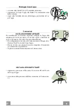
ELECTRICAL CONNECTION 

• Connect the hood to the mains through a two-pole switch hav-

ing a contact gap of at least 3 mm.

• Remove  the  grease  filters  (see  paragraph  Maintenance)  being

sure that the connector of the feeding cable is correctly inserted
in the socket placed on the side of the fan.

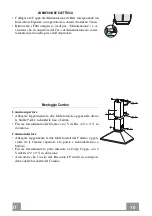
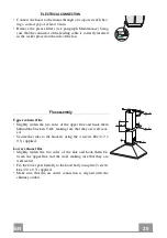
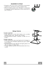
Flue assembly 

Upper exhaust flue 

• Slightly widen the two sides of the upper flue and hook them

behind the brackets 

7.2.1

, making sure that they are well seat-

ed.

• Secure the sides to the brackets using the 4 screws 

12c

 (2,9 x

9,5) supplied.

Lower exhaust flue 

• Slightly  widen  the  two  sides  of  the  flue  and  hook  them  be-

tween  the  upper  flue  and  the  wall,  making  sure  that  they  are
well seated.

• Fix the lower part laterally to the hood body using the 2 screws

12c 

(2,9 x 9,5) supplied.

• Make  sure  that  the  air  outlet  connection  is  aligned  with  the

chimney outlets.

12c

12c

12c

2.2

2.1

2

Summary of Contents for 991.0536.838

Page 1: ...Libretto di Istruzioni Instructions Manual Manuel d Instructions Bedienungsanleitung Gebruiksaanwijzing Manual de instrucciones Manual de Instru es...

Page 2: ...ONSIGNES DE S CURIT 24 CARACTERISTIQUES 27 INSTALLATION 28 UTILISATION 31 ENTRETIEN 32 INHALTSVERZEICHNIS SICHERHEITSINFORMATIONEN 34 CHARAKTERISTIKEN 37 MONTAGE 38 BEDIENUNG 41 WARTUNG 42 INHOUDSOPGA...

Page 3: ...3 3 NDICE INFORMA ES DE SEGURAN A 64 CARACTER STICAS 67 INSTALA O 68 UTILIZA O 71 MANUTEN O 72 PT...

Page 4: ...lati a un altezza inferiore vedere il paragrafo relativo alle dimensioni di lavoro e all installazione Se le istruzioni di installazione del piano cottura a gas specificano una distanza maggiore di qu...

Page 5: ...r lo scarico dei fumi importante attenersi scrupolosamente ai regolamenti stabiliti dalle autorit locali AVVERTENZA prima di installare la cappa rimuovere le pellicole di protezione Usare solo viti e...

Page 6: ...zzano gas o altri combustibili non applicabile ad apparecchi che scaricano unicamente l aria nel locale Il simbolo sul prodotto o sulla sua confezione indica che il prodotto non pu essere smaltito com...

Page 7: ...ngia di Riduzione 150 120 mm 15 1 Raccordo Uscita Aria Rif Q t Componenti di Installazione 7 1 2 Staffe Fissaggio Corpo Cappa 7 2 1 2 Staffe Fissaggio Camino Superiore 11 8 Tasselli 12a 8 Viti 4 2 x 4...

Page 8: ...Verticale di riferimento e 210 mm sopra la linea Orizzontale di riferimento Segnare i centri dei Fori della Staffa Ripetere questa operazione dalla parte opposta FONDALE OPTIONAL Il Fondale va montato...

Page 9: ...tubazione di uscita per mezzo di un tubo rigido o flessibile di 150 o 120 mm la cui scelta lasciata all installatore Per collegamento con tubo 120 mm inserire la Flangia di ri duzione 9 sull Uscita de...

Page 10: ...uperiore Allargare leggermente le due falde laterali agganciarle dietro le Staffe 7 2 1 e richiuderle fino a battuta Fissare lateralmente alle Staffe con 4 Viti 12c 2 9 x 9 5 in dotazione Camino infer...

Page 11: ...e livel lo sonoro 3 Velocit massima adatta a fronteggiare le massime emissioni di vapore di cottura anche per tempi prolungati L Luci Accende e spegne l Impianto di Illuminazione S Led Led accensione...

Page 12: ...are i Filtri evitando di piegarli e lasciarli asciugare prima di rimontarli Rimontarli facendo attenzione a mantenere la maniglia verso la parte visibile esterna Filtri antiodore al Carbone attivo Ver...

Page 13: ...mpade e sostituirle con nuove di uguali caratteristiche Rimontare i Filtri antigrasso metallici Lampada Assorbimento W Attacco Voltaggio V Dimensione mm Codice ILCOS 4 E14 220 240 107 x 37 DRBB F 4 22...

Page 14: ...height please refer to the paragraphs on working dimensions and installation If the instructions for installation for the gas hob specify a greater distance this must be respected Check that the main...

Page 15: ...to be adopted for fume discharging it is important to closely follow the regulations provid ed by the local authorities WARNING Before installing the Hood remove the protective films Use only screws...

Page 16: ...els not applicable to appliances that only discharge the air back into the room The symbol on the product or on its packaging indicates that this product may not be treated as household waste Instead...

Page 17: ...Reducer Flange 150 120 mm 15 1 Air Outlet Connection Ref Q ty Installation Components 7 1 2 Hood Body Fixing Brackets 7 2 1 2 Upper Chimney Section Fixing Brackets 11 8 Wall Plugs 12a 8 Screws 4 2 x 4...

Page 18: ...acket 7 1 as shown 95 mm from the vertical reference line and 210 mm above the horizontal reference line Mark the centres of the holes in the bracket Repeat this operation on the other side REAR PANEL...

Page 19: ...ed version connect the hood to the chimney using either a flexible or rigid pipe 150 or 120 mm the choice of which is left to the installer To install a 120 mm air exhaust connection insert the reduc...

Page 20: ...htly widen the two sides of the upper flue and hook them behind the brackets 7 2 1 making sure that they are well seat ed Secure the sides to the brackets using the 4 screws 12c 2 9 x 9 5 supplied Low...

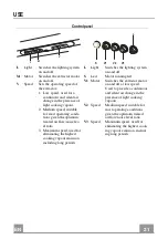
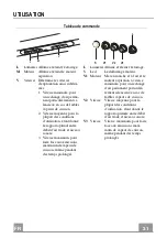
Page 21: ...treated air flow noise lev el ratio 3 Maximum speed used for eliminating the highest cooking vapour emission including long periods L Light Switches the lighting system on and off S Led Motor running...

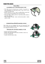
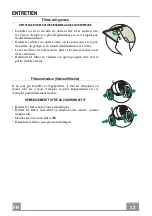
Page 22: ...filters taking care not to bend them Allow them to dry before refitting When refitting the filters make sure that the handle is visible on the outside Activated charcoal filter Recirculation version T...

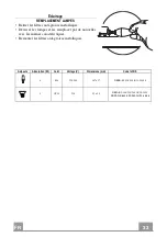
Page 23: ...bs and replace them with new ones having the same characteristics Replace the metal grease filters Lamp Power W Socket Voltage V Dimension mm ILCOS Code 4 E14 220 240 107 x 37 DRBB F 4 220 240 E14 35...

Page 24: ...r inf rieure voir le paragraphe concernant les dimensions de travail et l installation Si les instructions d installation du plan de cuisson gaz sp cifient une distance sup rieure celle indiqu e ci de...

Page 25: ...par les autorit s locales AVERTISSEMENT Avant d installer la hotte retirer les films de protection Utilisez exclusivement des vis et des petites fournitures du type adapt pour la hotte AVERTISSEMENT...

Page 26: ...e temps que des appareils utilisant du gaz ou d autres combustibles non applicable aux appareils qui vacuent l air uniquement dans la pi ce Le symbole marqu sur le produit ou sur son emballage indique...

Page 27: ...Inf rieure 9 1 Flasque de R duction 150 120 mm 15 1 Raccord Sortie Air R f Q t Composants pour l installation 7 1 2 Brides Fixation Corps Hotte 7 2 1 2 Brides Fixation Chemin e Sup rieure 11 8 Chevill...

Page 28: ...t 210 mm au dessus de la ligne horizontale de rep re Marquer les centres des trous de la bride R p ter cette op ration sur le c t oppos FIXATION EMBASE SI FOURNIE L Embase doit tre mont e avant d inst...

Page 29: ...de sortie au moyen d un tube rigide ou flexible de 150 ou 120 mm dont le choix est laiss l installateur Pour la liaison avec le tube 120 mm ins rer la buse de r duc tion 9 sur la sortie du corps de l...

Page 30: ...Elargir l g rement les deux bords lat raux et les accrocher derri re les brides 7 2 1 refermer jusqu la but e Fixer lat ralement aux brides l aide des 4 vis 12e 2 9 x 9 5 fournies Chemin e inf rieure...

Page 31: ...e d bit d air trait et niveau sonore 3 Vitesse maximum pour faire face aux missions maximum de vapeur de cuisson m me pendant des temps prolong s L Lumi res Allume et teint l clairage S Led Led alluma...

Page 32: ...res en vitant de les plier et les laisser s cher avant de les remonter Remonter les filtres en veillant ce que la poign e reste vers la partie visible externe Filtre anti odeur Version filtrante Il ne...

Page 33: ...et les remplacer par de nouvelles avec les m mes caract ristiques Remonter les filtres anti graisse m talliques Ampoule Absorption W Culot Voltage V Dimensions mm Code ILCOS 4 E14 220 240 107 x 37 DRB...

Page 34: ...ige Modelle k nnen auch niedriger installiert werden siehe Absatz Installation Sollten die Installationsanweisungen des gasbetriebenen Kochfelds einen gr eren Abstand als oben angegeben vorsehen ist d...

Page 35: ...hen Beh rden streng einzuhalten WARNUNG Bevor die Haube installiert wird die Schutzfolien abziehen Nur f r die Abzugshaube geeignete Schrauben und Kleinteile verwenden WARNUNG Die mangelnde Verwendung...

Page 36: ...e Brennstoffe benutzen muss im Raum eine ausreichende Bel ftung vorhanden sein gilt nicht f r Ger te die nur Luft in den Raum ablassen Schutzschild bei Rissbildung ersetzen Das Symbol am Produkt oder...

Page 37: ...9 1 Reduzierflansch 150 120 mm 15 1 Luftaustritt Anschlussst ck Pos St Montagekomponenten 7 1 2 Befestigungsb gel Haubenk rper 7 2 1 2 Befestigungsb gel oberer Kaminteil 11 8 D bel 12a 8 Schrauben 4...

Page 38: ...Bezugslinie und 210 mm oberhalb der horizontalen Bezugslinie auflegen Die Mittelpunkte der B gelbohrungen an der Wand markieren Gleicherma en an der gegen berliegenden Seite vorgehen R CKWANDPANEEL OP...

Page 39: ...aube vom Installateur wahlweise mittels Rohr oder Schlauch 150 oder 120 mm an die Au en rohrleitung angeschlossen werden Bei Verwendung eines Anschlussrohres 120 den Reduzier flansch 9 am Haubenaustri...

Page 40: ...nkel leicht auseinanderbiegen hinter den B geln 7 2 1 einh ngen und bis zum Anschlag wieder schlie en Bei den B geln mit Hilfe der 4 mitgelieferten Schrauben 12e 2 9 x 9 5 fixieren Unterer Kaminteil D...

Page 41: ...er uschentwicklung f r die meisten Anwendungs situationen 3 h chste Gebl sestufe eignet sich f r starke Kochdunstentwicklung auch ber l ngere Zeit hin L Beleucht Schaltet die Beleuchtung ein und aus S...

Page 42: ...gen und vor der Remontage trocknen lassen Bei der Remontage ist darauf zu achten dass sich der Griff auf der sichtbaren Au enseite befindet Geruchsfilter Umluftbetrieb Sie k nnen weder gewaschen noch...

Page 43: ...Lampen ausschrauben und durch gleichwertige ersetzen Die Metallfettfilter wieder montieren Lampe Leistung W Fassung Spannung V Gr e mm ILCOS Code 4 E14 220 240 107 x 37 DRBB F 4 220 240 E14 35 100 5...

Page 44: ...d zie de paragraaf over de werkafmetingen en de installatie Als de installatievoorschriften van de gaskookplaat bepalen dat een grote re afstand in acht moet worden genomen dan hierboven is aangegeven...

Page 45: ...e door de lokale autoriteiten zijn bepaald nauwgezet worden opgevolgd WAARSCHUWING verwijder de beschermfolie alvorens de afzuigkap te installeren Gebruik alleen schroeven en kleine onderdelen die ges...

Page 46: ...et apparaten op gas of andere brandstoffen wordt gebruikt niet van toepassing op apparaten die alleen lucht in de ruimte blazen Het symbool op het product of op de verpakking wijst erop dat dit produc...

Page 47: ...eductieflens 150 120 mm 15 1 Verbindingsstuk luchtuitlaat Ref Installatieonderdelen 7 1 2 Bevestigingsbeugels wasemkap 7 2 1 2 Bevestigingsbeugels bovenstuk van de schouw 11 8 Pluggen 12a 8 Schroeven...

Page 48: ...210 mm boven de horizontale referentielijn Teken de middelpunten van de gaten in de beugel af Herhaal deze handeling aan de andere kant MUURPLAAT OPTIONEEL De muurplaat moet gemonteerd worden voordat...

Page 49: ...oor middel van een starre of buigzame leiding van 150 of 120 mm naar keuze van de installateur Voor verbinding met een leiding van 120 mm moet de reductieflens 9 op de uitlaat van de wasemkap worden a...

Page 50: ...wee zijplaten enigszins openen ze vasthaken achter de beugels 7 2 1 en ze weer zo ver mogelijk sluiten Aan de zijkant aan de beugel bevestigen met de 4 bijgeleverde schroeven 12c Onderstuk van de scho...

Page 51: ...d behandelde lucht en het geluidsniveau 3 Maximumsnelheid geschikt om de grootste kookdampen tegen te gaan ook voor langere tijd L Lichten Hiermee schakelt u de verlichting aan en uit S Led Led motori...

Page 52: ...ermijd hierbij ze te buigen en laat ze drogen alvorens ze terug te plaatsen Plaats de vetfilters terug en let er hierbij op dat de handgreep zichtbaar blijft Geurfilter filterversie De filters kunnen...

Page 53: ...los en vervang ze door nieuwe lampen met dezelfde eigenschappen Plaats de metalen vetfilters terug Lamp Stroomopname W Aansluiting Voltage V Afmeting mm ILCOS code 4 E14 220 240 107 x 37 DRBB F 4 220...

Page 54: ...altura inferior v ase la secci n sobre dimensiones de trabajo e instala ci n Si en las instrucciones de montaje de la placa de cocci n a gas se indi ca una distancia mayor que la indicada anteriormen...

Page 55: ...os es importante cumplir escrupulosamente las normas establecidas por las autoridades locales ADVERTENCIA Retire la pel cula protectora antes de instalar la campana Utilice nicamente tornillos y herra...

Page 56: ...icen gas u otros combustibles no aplicable a los aparatos que s lo descargan aire en el local El s mbolo en el producto o en su embalaje indica que este producto no debe desecharse como residuo dom st...

Page 57: ...rior 9 1 Brida de reducci n 150 120 mm 15 1 Racor salida aire Ref Cant Componentes de Instalaci n 7 1 2 Bridas de fijaci n campana 7 2 1 2 Bridas de fijaci n chimenea superior 11 8 Tacoos 12a 8 Tornil...

Page 58: ...10 mm sobre la l nea horizontal de referencia Marcar los centros de los orificios de la brida Repetir esta operaci n en la parte opuesta FONDO OPCIONAL El fondo debe montarse antes de montar el cuerpo...

Page 59: ...la instalaci n de la versi n aspirante conectar la campana al tubo de salida mediante un tubo r gido o flexible de 150 o 120 mm a discreci n del instalador Para la conexi n con el tubo de 120 mm intro...

Page 60: ...char ligeramente las dos faldas laterales engancharlas detr s de las bridas 7 2 1 cerrarlas hasta el tope Fijar a los lados de las bridas con los 4 tornillos 12c 2 9 x 9 5 en dotaci n Chimenea inferio...

Page 61: ...de ruido 3 Velocidad m xima in dicada para hacer frente a grandes cantidades de vapor de cocci n incluso para tiempos prolongados L Luces Enciende y apaga la instala ci n de iluminaci n S Led Led de...

Page 62: ...se doblen y dejarlos secar antes de volverlos a montar Montar los filtros prestando atenci n en mantener la manija hacia la parte visible exterior Filtros antiolor Versi n filtrante No se pueden lava...

Page 63: ...ustituirlas con nuevas que tengan las mismas caracter sticas Montar nuevamente los filtros antigrasa met licos o cerrar la rejilla portafiltros L mpara Consumo de energ a W Casquillo Voltaje V Dimensi...

Page 64: ...er o ser instalados a altura inferior consulte o par grafo sobre as dimens es de trabalho e a instala o Se nas instru es de instala o da placa de cozinha a g s estiver especificada uma dist ncia maior...

Page 65: ...necess rio respeitar para evacuar o fumo importante seguir atentamente os regulamentos estabelecidos pelas autoridades locais ADVERT NCIA antes de instalar o exaustor retire as pel culas de prote o Ut...

Page 66: ...r for utilizado simultaneamente com aparelhos que utilizem g s ou outros combust veis n o aplic vel a aparelhos que apenas descarregam ar no aposento O s mbolo colocado no produto ou na sua embalagem...

Page 67: ...9 1 Flange de redu o 150 125 mm 15 1 Conex o da sa da de ar Ref Qtd Componentes de instala o 7 1 2 Suportes de fixa o da estrutura do exaustor 7 2 1 2 Suportes de fixa o da chamin superior 11 8 Bucha...

Page 68: ...linha de refer ncia horizontal Marque os centros dos furos do suporte Repita a opera o do lado oposto FUNDO ACESS RIO DE OP O O fundo deve ser montado antes da montagem do corpo do exaustor e se o uti...

Page 69: ...ustor ao tubo de sa da utilizando um tubo r gido ou flex vel de 150 ou 120 mm esta escolha deve ser feita pelo instalador Para a liga o com um tubo de 120 mm instale a flange de redu o 9 na sa da do c...

Page 70: ...e ligeiramente as duas folhas laterais prenda as atr s dos suportes 7 2 1 e volte a fech las completamente Fixe lateralmente aos suportes com os 4 parafusos 12c 2 9 x 6 5 fornecidos com o aparelho Cha...

Page 71: ...3 Velocidade m xima indicada para enfrentar as m ximas emiss es de vapores de cozedura mesmo durante per odos prolongados L Luzes Liga e desliga a Ilumina o S Led Led de liga o do motor V1 Motor Liga...

Page 72: ...de os instalar novamente certifique se de que ficam bem secos Ao instalar novamente os filtros certifique se de que a pega fica vis vel do exterior Filtro anti odor Vers o Filtrante N o pode ser lava...

Page 73: ...s l mpadas e substitua as por novas de caracter sticas iguais Reinstale os filtros met licos antigordura ou feche a grade porta filtros L mpada Absor o W Liga o Tens o V Dimens o mm C digo ILCOS 4 E14...

Page 74: ......

Page 75: ......

Page 76: ...991 0536 838_ver2 190409 D000000004418_01...

Reviews: