28
Version 07/11 - Page 5
9.0 feet
10.0 feet
0.0 feet
19.0 feet
TOOLS NEEDED FOR INSTALLATION
• Saber Saw or Jig Saw
• Drill
• 1 1/4" Wood Drill Bit
• Pliers
• Phillips Screwdriver
• Wire Stripper or Utility Knife
• Metal Snips
• Measuring Tape or Ruler
• Level
• Pencil
• Caulking Gun
• Duct Tape
PARTS SUPPLIED FOR INSTALLATION
• 1 Backdraft Damper
• 1 Vent Grate (for recirculating installations only)
• 1 Rear Trim Strip (for back of the hood)
• 1 Literature Package
PARTS NEEDED FOR INSTALLATION
• 2 Conduit Connectors
• Power Supply Cable
• 1 Wall or Roof Cap
• All Metal Ductwork
OPTIONAL ACCESSORIES AVAILABLE
• Charcoal Filters
For non-vented installations only,
replace charcoal filters as needed
part #
FILTER1
PLAN THE DUCTWORK
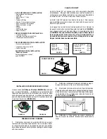
The Cristal 24" slideout rangehood is designed to offer wide flexibility of installations.
The rangehood can be ducted vertically through a 6" round vent. The unit can also
be installed in a recirculating configuration. The unit comes standard in the top
venting position.
FIGURES 1
shows vertical installations for this unit.
FIGURE
2
shows recirculating installation.
The Cristal 24" requires 6" round ductwork. To ensure that the blower performs
to its highest possible capacity, ductwork should be as short and straight as
possilbe.
RECIRCULATING INSTALLATIONS
For recirculating installations
(FIGURE 2)
,
Charcoal Filters
are necessary. Remove the two grease filters and set aside. Attach
one charcoal filter to each end of the blower. Each charcoal filter attaches to the black grid on the side of the blower. Rotate
the filter clockwise to install and counterclockwise to remove
(FIGURE 2A)
. Replace the two grease filters.
Some ductwork
must be installed
to exhaust the rangehood back into the kitchen, either at the top of the cabinet or at the face of the soffit. A
plastic vent grate
(FIGURE 2B)
supplied with the rangehood can be used to cover the duct opening. This duct work must not
terminate into a dead air space.
FIGURE 2A
45˚ Elbow
90˚ Elbow
90˚ Flat Elbow
Wall Cap
FIGURE A
9 Feet Straight Duct
2 - 90˚ Elbows
Wall Cap
Total System
FIGURE B
3.0 feet
5.0 feet
12.0 feet
0.0 feet
VERTICAL
DUCTING
FIGURE 1
cabinet
ceiling
6” round
duct
hood
cabinet
ceiling
6” round
duct
hood
soffit
vent grate
vent grate
FIGURE 2B
FIGURE 2
The ductrun should not exceed 35 feet if ducted with
the required minimum of 6" round duct. Calculate
the length of the ductwork by adding the equiva-
lent feet in
FIGURE A
for each piece of duct in
the system An example is given in
FIGURE B
.
For best results, use no more than three 90°
elbows. Make sure that there is a minimum of
24" of straight duct between elbows if more
than one is used. Do not install two elbows
together. If you must elbow right away, do it
as far away from the hood's exhaust opening
as possible.
EN
1
2
12
CARE
Grease filters
CLEANING METAL SELF- SUPPORTING GREASE FILTERS
• The filters must be cleaned every 2 months of operation, or
more frequently for particularly heavy usage, and can be
washed in a dishwasher.
• Remove the filters one at a time by pushing them towards the
back of the group and pulling up at the same time.
• Wash the filters, taking care not to bend them. Allow them to
dry before refitting.
• When refitting the filters, make sure that the handle is visible
on the outside.
Activated charcoal filter (Recirculating version)
These filters (not supplied with the rangehood)are not washable
and cannot be regenerated, and must be replaced approximately
every 4 months of operation, or more frequently with heavy us-
age.
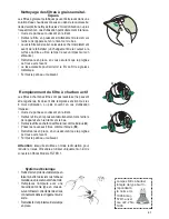
REPLACING THE ACTIVATED CHARCOAL FILTER
• Remove the metal grease filters
• Remove the saturated activated charcoal filter as shown (
A
).
• Fit the new filters (
B
).z
• Replace the metal grease filters.
�
�
Lighting
LIGHT REPLACEMENT
20 W halogen light.
• Remove the 2 screws fixing the Lighting support, and pull it
out of from the Hood.
• Extract the lamp from the Support.
• Replace with another of the same type, making sure that the
two pins are properly inserted in the lamp holder socket holes.
• Replace the Support, fixing it in place with the two screws re-
moved as above.
HERRAMIENTAS NECESARIAS PARA LA INSTA-
LACIÓN
• Sierra de sable o sierra de calar
• Taladro
• Broca para madera de 1 1/4"
• Alicates
• Destornillador Phillips
• Pelacables o cuchillo de uso general
• Tijeras de metal
• Cinta métrica o regla
• Nivel
• Lápiz
• Pistola de calafateo
• Cinta adhesiva
PIEZAS SUMINISTRADAS PARA LA INSTA-
LACIÓN
• 1 Registro de contraflujo
• 1 Rejilla de ventilación (sólo para instalaciones de
recirculación)
• 1 Tira de ajuste trasera (para la parte posterior de la
campana)
• 1 Paquete de documentación
PIEZAS NECESARIAS PARA LA INSTALACIÓN
• 2 Conectores de conducto
• 1 Tapa de pared o techo
• Todos los conductos metálicos
ACCESORIOS OPCIONALES DISPONIBLES
• Filtros de carbón
Para instalaciones sin ventilación solamente, reem-
place los filtros de carbón según sea necesario parte
# FILTER1
PLANEAR EL CONDUCTO
La gama de campanas deslizantes Cristal 24" está diseñada para
ofrecer una amplia flexibilidad de instalación. La campana puede
ser canalizada verticalmente a través de una ventilación redonda
de 6". La unidad también se puede instalar en una configuración de
recirculación. La unidad viene de serie en la posición de ventilación
superior. La FIGURA 1 muestra las instalaciones verticales para
esta unidad. La FIGURA 2 muestra la instalación de recirculación.
La Cristal 24" requiere conductos redondos de 6". Para asegurar
que el ventilador funcione al máximo de su capacidad, los conductos
deben ser tan cortos y rectos como sea posible.
El recorrido del conducto no debe exceder los 35 pies si se coloca
con un mínimo requerido de 6" de conducto redondo. Calcule la
longitud del conducto añadiendo los pies equivalentes en la FIGURA
A para cada pieza del conducto en el sistema. Un ejemplo se da en
la FIGURA B. Para mejores resultados, no use más de tres codos
de 90°. Asegúrese de que haya un mínimo de 24" de conducto recto
entre los codos si se usa más de uno. No instale dos codos juntos.
Si debe colocar el codo inmediatamente, hágalo tan lejos de la
abertura de escape de la campana como sea posible.
Codo de 45 °
3.0 pies
Codo de 90°
5.0 pies
Codo plano de 90 ° 12.0 pies
Tapa de pared
0.0 pies
FIGURA A
9 pies conducto recto 9.0 pies
2 - Codos de 90°
10.0 pies
Tapa de pared
0.0 pies
Sistema total
19.0 pies
FIGURA B
Version 07/11 - Page 5
9.0 feet
10.0 feet
0.0 feet
19.0 feet
TOOLS NEEDED FOR INSTALLATION
• Saber Saw or Jig Saw
• Drill
• 1 1/4" Wood Drill Bit
• Pliers
• Phillips Screwdriver
• Wire Stripper or Utility Knife
• Metal Snips
• Measuring Tape or Ruler
• Level
• Pencil
• Caulking Gun
• Duct Tape
PARTS SUPPLIED FOR INSTALLATION
• 1 Backdraft Damper
• 1 Vent Grate (for recirculating installations only)
• 1 Rear Trim Strip (for back of the hood)
• 1 Literature Package
PARTS NEEDED FOR INSTALLATION
• 2 Conduit Connectors
• Power Supply Cable
• 1 Wall or Roof Cap
• All Metal Ductwork
OPTIONAL ACCESSORIES AVAILABLE
• Charcoal Filters
For non-vented installations only,
replace charcoal filters as needed
part #
FILTER1
PLAN THE DUCTWORK
The Cristal 24" slideout rangehood is designed to offer wide flexibility of installations.
The rangehood can be ducted vertically through a 6" round vent. The unit can also
be installed in a recirculating configuration. The unit comes standard in the top
venting position.
FIGURES 1
shows vertical installations for this unit.
FIGURE
2
shows recirculating installation.
The Cristal 24" requires 6" round ductwork. To ensure that the blower performs
to its highest possible capacity, ductwork should be as short and straight as
possilbe.
RECIRCULATING INSTALLATIONS
For recirculating installations
(FIGURE 2)
,
Charcoal Filters
are necessary. Remove the two grease filters and set aside. Attach
one charcoal filter to each end of the blower. Each charcoal filter attaches to the black grid on the side of the blower. Rotate
the filter clockwise to install and counterclockwise to remove
(FIGURE 2A)
. Replace the two grease filters.
Some ductwork
must be installed
to exhaust the rangehood back into the kitchen, either at the top of the cabinet or at the face of the soffit. A
plastic vent grate
(FIGURE 2B)
supplied with the rangehood can be used to cover the duct opening. This duct work must not
terminate into a dead air space.
FIGURE 2A
45˚ Elbow
90˚ Elbow
90˚ Flat Elbow
Wall Cap
FIGURE A
9 Feet Straight Duct
2 - 90˚ Elbows
Wall Cap
Total System
FIGURE B
3.0 feet
5.0 feet
12.0 feet
0.0 feet
VERTICAL
DUCTING
FIGURE 1
cabinet
ceiling
6” round
duct
hood
cabinet
ceiling
6” round
duct
hood
soffit
vent grate
vent grate
FIGURE 2B
FIGURE 2
The ductrun should not exceed 35 feet if ducted with
the required minimum of 6" round duct. Calculate
the length of the ductwork by adding the equiva-
lent feet in
FIGURE A
for each piece of duct in
the system An example is given in
FIGURE B
.
For best results, use no more than three 90°
elbows. Make sure that there is a minimum of
24" of straight duct between elbows if more
than one is used. Do not install two elbows
together. If you must elbow right away, do it
as far away from the hood's exhaust opening
as possible.
EN
1
2
12
CARE
Grease filters
CLEANING METAL SELF- SUPPORTING GREASE FILTERS
• The filters must be cleaned every 2 months of operation, or
more frequently for particularly heavy usage, and can be
washed in a dishwasher.
• Remove the filters one at a time by pushing them towards the
back of the group and pulling up at the same time.
• Wash the filters, taking care not to bend them. Allow them to
dry before refitting.
• When refitting the filters, make sure that the handle is visible
on the outside.
Activated charcoal filter (Recirculating version)
These filters (not supplied with the rangehood)are not washable
and cannot be regenerated, and must be replaced approximately
every 4 months of operation, or more frequently with heavy us-
age.
REPLACING THE ACTIVATED CHARCOAL FILTER
• Remove the metal grease filters
• Remove the saturated activated charcoal filter as shown (
A
).
• Fit the new filters (
B
).z
• Replace the metal grease filters.
�
�
Lighting
LIGHT REPLACEMENT
20 W halogen light.
• Remove the 2 screws fixing the Lighting support, and pull it
out of from the Hood.
• Extract the lamp from the Support.
• Replace with another of the same type, making sure that the
two pins are properly inserted in the lamp holder socket holes.
• Replace the Support, fixing it in place with the two screws re-
moved as above.
INSTALACIONES DE RECIRCULACIÓN
Para las instalaciones de recirculación (FIGURA 2), se necesitan filtros de carbón. Retire los dos filtros de grasa y
déjelos a un lado. Conecte un filtro de carbón a cada extremo del soplador. Cada filtro de carbón se conecta a la
rejilla negra en el costado del ventilador. Gire el filtro en el sentido horario para instalarlo y en sentido antihorario
para extraerlo (FIGURA 2A). Reemplace los dos filtros de grasa. Algunos conductos deben ser instalados para que
la campana vuelva a la cocina, ya sea en la parte superior del armario o en la cara del sofito. Para cubrir la abertura
del conducto se puede utilizar una rejilla de ventilación de plástico (FIGURA 2B) suministrada con la campana. Este
trabajo de conductos no debe terminar en un espacio de aire muerto.
Techo
Sofito
Rejilla de
ventilación
Summary of Contents for Cristal 24 SS
Page 35: ...35...

