15
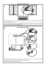
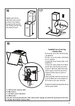
Mark the wall where indicated, 13
1/4
" above the horizontal line and at 6
7/16
" distance on the left
and right of vertical line. Checking that the two marks are level.
Insert two wall plugs into the holes as shown.
Place a bracket 7.2.1 on the wall as shown about 1 1/8" from the ceiling or upper limit, aligning the
center (notch) with the vertical reference line and mark the wall at the centers of the holes in the bracket.
Place the second bracket 7.2.1 on the wall as shown, below the first bracket, at the height of the
upper chimney section supplied and aligning the center (notch) with the vertical line.
Mark the wall at the centers of the holes in the bracket and drill ø 5/16" as shown.
Installation screws provided for the Brackets, must be secured with wall plugs (purchased separately).
Cooker Hood Installation with optional Chimney
[
[
[
´
´
!
´
´
´
´
[
[
´
´
2.2
2.1
2.1
2.1
Summary of Contents for CTAL31BK300-B
Page 5: ...5 RANGEHOOD DIMENSIONS ELECTRICAL CONNECTION KNOCKOUT...
Page 6: ...6 Min 21 3 16 Min 24...
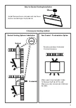
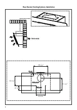
Page 9: ...9 Rear Ducted Venting Options Installation Horizontal...
Page 21: ...21 Wiring Diagram...
Page 26: ...26 DIMENSIONS DE LA HOTTE DIMENSION L ENTR E LECTRIQUE D FON ABLE...
Page 27: ...27 Min 24 Min 24...
Page 30: ...30 Horizontale Options d installation avec ventilation canalis e vers l arri re...
Page 42: ...42 Sch ma de c blage...


