background image


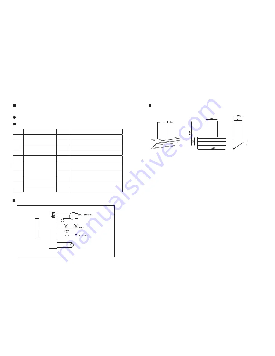
μ

Switch

Circuit Board

Control

Wiring

Brown

Motor

Sreen

Panel

Motor

Capacitance

Blue

Green-and-yellow

Light

Red

The parts or electric wires are subject to change without notice

Black

Red

Black

Green

White

Yellow

Orange

Brown

Black

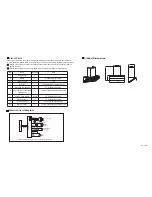
Electric Circuit Diagram

List of Parts

Product Dimensions

Unit: mm

Please go through the list of parts to be assembled and ensure that all parts are accounted for 

in good condition. Should there be any missing or damaged parts, kindly take the following actions:

No.

Name

Quantity

1

1

1

1
1

1

4 each

4
2

2

1

2

3

4
5

6

7

8
9

10

Range hood

Manual

Exhaust pipe

Oil catch

Mounting component

Securing bar for extended

chimney flue

Screws, flat washers

Plastic anchors

ST4.2x8 screws

M4x10 screws

Please keep it properly

1.5 m

To be installed on the range hood

To install the appliance

To secure the extended chimney flue

To install the appliance

To install the appliance

To secure the exhaust pipe

To secure the extended chimney flue

Note

Should our company or vendor be liable, please contact the vendor and request for them to 

handle the issue.
Should the customer be personally liable, please contact the vendor or our company.

Summary of Contents for FABERJET SENSO

Page 1: ...afe place in order that full advantage can be taken of the feature of your glass hob Designer Hood Instruction Manual FABERJET SENSO 220V 240V 50Hz 220W 2X2W L 898 355 H 785 W 380Pa 68dB Technical Specifications Model Voltage Motor Input Light Air Pressure Max Noise Outer Dimensions ...

Page 2: ...following actions No Name Quantity 1 1 1 1 1 1 4 each 4 2 2 1 2 3 4 5 6 7 8 9 10 Range hood Manual Exhaust pipe Oil catch Mounting component Securing bar for extended chimney flue Screws flat washers Plastic anchors ST4 2x8 screws M4x10 screws Please keep it properly 1 5 m To be installed on the range hood To install the appliance To secure the extended chimney flue To install the appliance To ins...

Page 3: ...re the upper chimney flue 10 mm diameter 4 keyholes to secure the appliance 10 mm diameter Power socket The pan surface The installation position for the mounting component of the chimney flue top view diagram Diagram of the air chamber outlet installed on top of the kitchen cabinet The lowest part of the range hood should be installed 500 550mm above the cooking surface or at the same level as th...

Page 4: ...them with a soft cloth Electrical parts are to be cleaned with a dry and soft cloth or soft brush and are not to be cleaned with water or a cleansing agent Failure to follow the instructions in this manual might result in the risk of the cooker hood catching fire Using the Appliances Control Panel with Delay Timer Function Power Delay Timer Light Low Speed High Speed Turbo Speed Operating the Appl...

Reviews: