background image

18

VEUILLEZ LIRE ET CONSERVER LA PRÉSENTE NOTICE AVANT DE 

COMMENCER L'INSTALLATION DE LA HOTTE DE CUISINE

AVERTISSEMENT:-POUR RÉDUIRE LE RISQUE D'UN FEU DE GRAISSE SUR LA TABLE DE 

CUISSON :  

a) Ne laissez jamais sans surveillance les éléments de la surface de cuisson à température 

élevée. Les bouillonnements excessifs peuvent provoquer de la fumée et les débordements 

de graisse peuvent s'enflammer.  L'huile doit être chauffée lentement, à une température 

basse ou moyenne.  

b) Assurez-vous de toujours mettre en marche le ventilateur de la hotte lorsque vous cuisinez 

à température élevée ou préparez un mets flambé (p.ex. crêpes Suzette, cerises jubilé, bœuf 

flambé).  

c) Nettoyez régulièrement les ventilateurs d'aspiration.  Assurez-vous de ne pas laisser de la 

graisse s'accumuler sur le ventilateur ou le filtre.  

d) Utilisez toujours des poêles et casseroles de la taille appropriée.  Utilisez toujours des 

ustensiles de cuisine de la taille adaptée à celle de l'élément chauffant.

AVERTISSEMENT : - POUR PRÉVENIR LES BLESSURES EN CAS DE FEU DE GRAISSE SUR 

LA TABLE DE CUISSON, SUIVEZ LES RECOMMANDATIONS SUIVANTES* :  

a) ÉTOUFFEZ LES FLAMMES à l'aide d'un couvercle hermétique, d'une plaque à biscuits ou 

d'un plateau métallique, puis éteignez le brûleur.  FAITES ATTENTION AUX BRÛLURES.  Si 

le feu ne s'éteint pas immédiatement, QUITTEZ LES LIEUX ET APPELEZ LES POMPIERS.  

b) NE PRENEZ JAMAIS UNE CASSEROLE EN FLAMME - Vous pourriez vous brûler.  

c) N'UTILISEZ JAMAIS DE L'EAU, ni un linge à vaisselle ou un torchon mouillé, pour éteindre 

le feu. Cela pourrait provoquer une violente explosion de vapeur.

d) Utilisez un extincteur UNIQUEMENT si : 

    1.  Vous êtes certain qu'il s'agit d'un extincteur de classe ABC et que vous connaissez bien 

son mode d'emploi.  

    2.  Le feu est de faible intensité et se limite à l'endroit où il a démarré.  

    3.  Les pompiers ont déjà été appelés.  

    4.  Une voie de sortie se trouve derrière vous pendant que vous éteignez les flammes

* D'après le guide « Kitchen Firesafety Tips » publié par la NFPA aux États-Unis

AVERTISSEMENT - POUR RÉDUIRE LE RISQUE D'INCENDIE OU DE CHOC ÉLECTRIQUE, 

n'utilisez jamais ce ventilateur en association avec un dispositif de réglage de vitesse à se-

mi-conducteurs.

AVERTISSEMENT - POUR RÉDUIRE LES RISQUES D'INCENDIE, DE CHOC ÉLECTRIQUE 

OU DE BLESSURE CORPORELLE, RESPECTEZ LES INSTRUCTIONS SUIVANTES :  

a. Utilisez cet appareil uniquement de la façon prévue par le fabricant. Pour toute question, 

communiquez avec le fabricant.

b. Avant de procéder à l'entretien ou au nettoyage de l'appareil, coupez l'alimentation au 

niveau du panneau électrique et verrouillez-le pour vous assurer que l'électricité n'est pas 

rétablie accidentellement. 

  S'il n'est pas possible de verrouiller le dispositif d'interruption de l'alimentation, affichez 

de façon ferme et bien visible un avis de danger, par exemple à l'aide d'une étiquette sur le 

panneau.

ATTENTION : Destiné à un usage de ventilation générale uniquement.  N'utilisez pas ce dis-

positif pour l'aspiration de vapeurs ou de matériaux dangereux ou explosifs.

AVERTISSEMENT - POUR RÉDUIRE LES RISQUES D'INCENDIE, DE CHOC ÉLECTRIQUE 

OU DE BLESSURE CORPORELLE, RESPECTEZ LES INSTRUCTIONS SUIVANTES : 

1. 

L'installation et le branchement électrique doivent être réalisés par un technicien qualifié 

et conformément à tous les codes et normes en vigueur, incluant ceux concernant la 

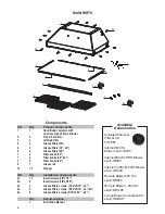
Summary of Contents for INCA PRO PLUS

Page 1: ...L3019SSNB B INPL3619SSNB B INPL3622SSNB B INPL4219SSNB B INPL4819SSNB B INPL4822SSNB B Installation Instructions Use and Care Information Instructions d installation Utilisez et d entretien INCA PRO P...

Page 2: ...ou can fight the fire with your back to an exit Based on Kitchen Firesafety Tips published by NFPA WARNING TO REDUCE THE RISK OF FIRE OR ELECTRIC SHOCK do not use this fan with any solid state speed c...

Page 3: ...ze conduction of outside temperatures as part of the vent system The damper should be on the cold air side of the thermal break The break should be as close as possible to where the vent system enters...

Page 4: ...ld be connected directly to the fused disconnect or circuit breaker through flexible armored or nonmetallic sheathed copper cable Allow some slack in the cable so the appliance can be moved if servici...

Page 5: ...3 46 9 16 A4 29 1 2 A1 35 1 2 A2 41 9 16 A3 47 9 16 A4 1 2 20 11 16 19 11 16 15 5 16 10 13 16 18 11 16 22 1 2 A1 34 9 16 A2 7 15 16 1 2 3 1 8 11 34 1 2 A1 46 9 16 A2 35 1 2 A1 47 9 16 A2 1 2 23 11 16...

Page 6: ...ts 9c 14 Install screws 1 8 x1 4 9d 6 Install screws 1 8 x5 16 9e 4 Grease filters screws 3 16 x5 16 30 9e 6 Grease filters screws 5 32 x5 16 36 42 9e 8 Grease filters screws 5 32 x5 16 48 Qty Documen...

Page 7: ...cabinet Replace as needed with the same model part FILTER1 NOTE The charcoal lter kit for use with the 300 600 cfm internal blower kit ONLY CAUTION To reduce risk of re and electric shock install this...

Page 8: ...alculate the length of the ductwork by adding the equivalent feet in FIGURE 5 for each piece of duct in the system An example is given in FIGURE 6 For best results use no more than three 90 elbows Mak...

Page 9: ...ed inside of Kit Internal 300 cfm Blower sku IB300 or Internal 600 cfm PRO Blower sku IB600 Connect the 6 hole end to the wire box and connect the 9 hole end to the motor Figure 5 FIGURE 4 6 hole end...

Page 10: ...ow steps 6 9 on the previous page to connect ducting wiring and test the electrical connection FIGURE 14 B Version 07 11 Page 9 INSTALLATION WITH IB1200 INTERNAL BLOWER 1200 cfm 1 Install the Plate B...

Page 11: ...he wiring box connected to the inside wall of the hood which connects to the home power supply thru the knockout on the side of the hood FIGURE 21 B 4 Pass the remote blower cable through the knockout...

Page 12: ...base to insure proper alignment of the two side clips After the Insert Hood is installed into the cabinet opening lock it into position by tightening the indicated screws in each of the two side stop...

Page 13: ...ower supply to the Black lead of the rangehood B with a twist on type wire connector C Connect the Green E Green and Yellow ground wire under the Green grounding screw Replace the field wiring compart...

Page 14: ...ng Activated Charcoal Filter The Activated Charcoal Filters are not washable and cannot be regenerated and should be replaced approximately every 4 months of operation or more frequently with heavy us...

Page 15: ...from the lter the knobs need to be installed onto the lter with 2 screws to each lter Install the grease rail into the back of the hood into the slots on the inside oor of the rear of the hood The Gre...

Page 16: ...16 Wiring Diagram...

Page 17: ...om accident alteration misuse abuse fire flood acts of God improper installation installation not in accordance with electrical or plumbing codes or Faber documentation or use of products not approved...

Page 18: ...apeur d Utilisez un extincteur UNIQUEMENT si 1 Vous tescertainqu ils agitd unextincteurdeclasseABCetquevousconnaissezbien son mode d emploi 2 Le feu est de faible intensit et se limite l endroit o il...

Page 19: ...rminez quelle m thode de ventilation est mieux adapt e votre application Les conduits peuvent passer par le mur ou le toit Pour garantir une meilleure efficacit la longueur des conduits et le nombre d...

Page 20: ...il si des travaux d entretien s av raient n cessaires Un raccord de conduit homologu par l UL de 1 2 doit tre install aux deux extr mit s du c ble d alimentation au niveau de l appareil et de la bo te...

Page 21: ...46 9 16 A4 29 1 2 A1 35 1 2 A2 41 9 16 A3 47 9 16 A4 1 2 20 11 16 19 11 16 15 5 16 10 13 16 18 11 16 22 1 2 A1 34 9 16 A2 7 15 16 1 2 3 1 8 11 34 1 2 A1 46 9 16 A2 35 1 2 A1 47 9 16 A2 1 2 23 11 16 2...

Page 22: ...ion 1 8 x1 4 9d 6 Vis d installation 1 8 x5 16 9e 4 Vis des filtres graisse 3 16 x5 16 30 9e 6 Vis des filtres graisse 5 32 x5 16 36 42 9e 8 Vis des filtres graisse 5 32 x5 16 48 Qt Documentation 1 In...

Page 23: ...r is compatible with this hood except for the kits below IB300 Internal Blower Kit 300 cfm IB600 Internal Blower Kit 600 cfm IB1200 Internal Blower Kit 1200 cfm RB900 Remote Blower Kit 900 cfm RB1200...

Page 24: ...DES RAILS DE GRAISSE ET DES FILTRES DE GRAISSE FIGURE 1 PLAN DU CONDUIT Pour assurer que le ventilateur marche le mieux le conduit doit tre aussi court et aussi droit que possible Le ductrun ne devrai...

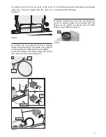
Page 25: ...la trousse du ventilateur interne 300 PCM n d article IB300 ou du venti lateur interne 600 PCM PRO n d article IB600 Figure 6 FIGURE 4 Extr mit 9 orifices Extr mit 9 orifices Extr mit 6 orifices 4 Br...

Page 26: ...on FIGURE 14 FIGURE 20 B 4 Installez les 2 kits de moteur sur les c t s de la parenth se de ventilateur utilisant les 4 vis four nies avec le kit de moteur Figure 10 7 Suivez la proc dure d crite l ta...

Page 27: ...e electrical connection Use the wiring box connected to the inside wall of the hood which connects to the home power supply thru the knockout on the side of the hood FIGURE 21 B 4 Faites passer le c b...

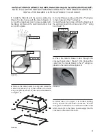
Page 28: ...garantir un alignement correct des deux fixations lat rales Lorsque la hotte encastrable est install e dans l ouverture de l armoire fixez la en serrant sous la hotte encastrable les vis indiqu es sur...

Page 29: ...un connecteur verrouill par rotation C Branchez le fil vert E vert et jaune de mise la terre sous la vis de mise la terre verte Remettez le couvercle du compartiment des c blages externes et les filt...

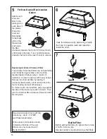
Page 30: ...e pour l enlever Remplacement du filtre charbon actif Les filtres charbon actif ne sont pas lavables et ne peuvent tre r g n r s Ils devraient tre remplac s environ tous les 4 mois d utilisation ou pl...

Page 31: ...ation Removal Remove the plastic from the lter the knobs need to be installed onto the lter with 2 screws to each lter Install the grease rail into the back of the hood into the slots on the inside oo...

Page 32: ...32 Sch ma de c blage...

Page 33: ...es d coulant d un accident d une modification de l utilisation incorrecte ou abusive d un incendie d une inondation d un cas de force majeure d une installation inad quate d une installation non confo...

Page 34: ......

Page 35: ......

Page 36: ...991 0463 718_01 170516 D003712_00...

Reviews: