


54
PARA LA INSTALACIÓN CON FORROS
Siempre siga todos los códigos y estándares aplicables
al construir una campana personalizad.
ADVERTENCIA
!
La Inca Smart puede ser utilizada
en gabinetes estándar de 30" o
36" de ancho o con campanas
personalizadas de 30" de ancho
y más.
Para campanas de madera o
a medida, elija SU PROPIO
revestimiento a medida o
nuestro revestimiento estándar
diseñado para instalaciones
de 30" y 36" de ancho. Los
forros crean un acabado
perfectamente sellado e
incombustible para la parte
inferior de su campana de
madera personalizada.
Los forros estándar se
componen de dos secciones:
una sección trasera más
grande (pre recortada para la
inserción de la Inca Smart) y
una sección frontal para una
profundidad ajustable total
entre 16" y 17 7/8".
!!! NOTA IMPORTANTE: NO
RETIRE LA SECCIÓN PERFORADA
ADICIONAL ALREDEDOR DEL
PRE-CORTE CUANDO INSTALE
EL FORRO ESTÁNDAR CON EL
MODELO INCA SMART.
Considere la forma, tamaño
y peso de la Inca Smart y
el Forro para determinar la
configuración de la campana
de madera/personalizada.
Ver DIMENSIONES DE LA
CAMPANA EXTRACTORA Y DEL
FORRO.
1. La campana personalizada/de madera debe tener una base resistente
(se recomienda madera contrachapada de 3/4 ") para alojar el recorte
para Inca Smart. La base debe estar rebajada para alojar la altura del
forro (
consulte DIMENSIONES DEL FORRO
). El forro se fija a la parte
inferior de la base con tornillos adecuados para el tamaño y el material
de la campana de madera/personalizada.
La Inca Smart se inserta en el recorte en el forro y la base.
2. Coloque la sección posterior del forro de forma que quede en el borde
posterior de la campana de madera/personalizada. Con un bolígrafo,
trace el contorno del pre recorte. Retire el forro y proceda a HACER LOS
RECORTES.
Instale ambas secciones del forro y proceda a
INSTALAR LA
CAMPANA EXTRACTORA
.
Version 09/14 - Page 5
The Inca Smart requires 5" round ductwork. To ensure that the blower performs to its
highest possible capacity, ductwork should be as short and straight as possilbe.
Make your ductrun as straight and short as possible. The ductrun should not exceed 25
equivalent feet if ducted with the required minimum of 5" round duct. Count 45º angles
as 3 feet, 90º elbows as 5 feet, and 90º flat elbows as 12 feet.
For best results, use no more than three 90° elbows. Make sure that there is a
minimum
of 24" of straight duct between elbows if more than one is used.
Do not install two
elbows together.
If you must elbow right away, do it as
far away
from the hood's
exhaust opening as possible.
TOOLS NEEDED FOR INSTALLATION
• Saber Saw or Jig Saw
• Drill
• 1 1/4" Wood Drill Bit
• Pliers
• Phillips Screwdriver
• Wire Stripper or Utility Knife
• Metal Snips
• Measuring Tape or Ruler
• Level
• Pencil
• Caulking Gun
• Duct Tape
PLAN YOUR DUCTWORK
The Inca Smart can be used in
standard 30" or 36" wide cabinetry
or with custom hoods 30" wide
and up.
For custom/wood hoods, choose
either YOUR OWN custom liner or
our Standard Liner designed for 30"
and 36" wide installations. Liners
create a perfectly-sealed, non-
combustible finish for the underside
of your custom/wood hood.
The Standard Liners are made
up of two sections: a larger, rear
section (pre-cut out for insertion of
the Inca Smart) and a front section
for a total adjustable depth between
16" and 17
7/8"
.
!!! IMPORTANT NOTE:
DO NOT
REMOVE THE ADDITIONAL
P E R F O R AT E D S E C T I O N
AROUND THE PRE-CUT-
OUT WHEN INSTALLING
THE STANDARD LINER WITH
THE INCA SMART MODEL.
THIS PERFORATION IS ONLY
REMOVED FOR USE WITH THE
INCA HC SS MODEL.
Consider the shape, size, and
weight of the Inca Smart and Liner
to determine the configuration
of the custom/wood hood. See
RANGEHOOD DIMENSIONS AND
LINER DIMENSIONS
on Page 4.
FOR INSTALLATIONS WITH LINERS
PARTS SUPPLIED FOR INSTALLATION
• 1 Backdraft Damper
• 10 Screws
• Field Wiring Box
• 1 Literature Package
PARTS NEEDED FOR INSTALLATION
• 2 Conduit Connectors
• Power Supply Cable
• Scews for Field Wiring Box
• 1 Wall or Roof Cap
• All Metal Ductwork
OPTIONAL ACCESSORIES AVAILABLE
•
Charcoal Filter Kit
For recirculating installations only,
replace charcoal filters as needed
part # FILTER4
•
Liners
Create a perfectly-sealed, non-combustible
perimeter around the Inca Smart. Depth adjustable
from 16" - 17
7/8"
.
Standard Liner 30 Stainless - part #
LINE30ST
Standard Liner 36 Stainless - part #
LINE36ST
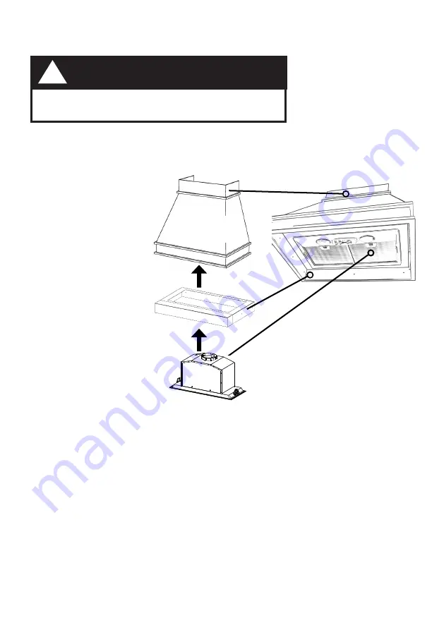
CUSTOM/WOOD
HOOD
STANDARD LINER
INCA SMART
WARNING
!
When building a custom hood,
always follow all applicable
codes and standards.
1.
The custom/wood hood must have a sturdy base (3/4" plywood recommended) to accomodate
the cut-out for the Inca Smart. The base must be recessed to accomodate the height of the
Liner (see
LINER DIMENSIONS
on Page 4). The Liner attaches to the bottom of the base
using screws appropriate for the size and material of your custom/wood hood. The Inca Smart
inserts into the cut-out in the Liner and base.
2.
Position the rear section of the Liner so that it abuts the back edge of your custom/wood
hood. Using a pen, trace the outline of the pre-cut out. Remove the Liner and proceed to
MAKE
YOUR CUT-OUTS
on Page 6. Install both sections of the Liner and proceed to I
NSTALL THE
RANGEHOOD
on Page 6.
CAMPANA DE
MADERA/
PERSONALIZADA
FORRO ESTÁNDAR
INCA SMART
Summary of Contents for INCA SMARTINSP28SS400
Page 5: ...5 RANGE HOOD DIMENSIONS 28 47...
Page 6: ...6 MIN 24 OVER ELECTRIC INSTALLATION HEIGHT REQUIREMENTS MIN 30 OVER GAS...
Page 27: ...27 DIMENSIONS HOTTE 28 47...
Page 49: ...49 DIMENSIONES DE LA CAMPANA EXTRACTORA 28 47...
Page 50: ...50 M N 24 SOBRE EL CTRICO REQUISITOS DE ALTURA DE INSTALACI N M N 30 SOBRE GAS...


