background image

31

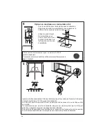
• Remove grease filters.

• Screw the Frame into place

12f

, re-

A

B

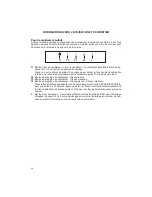
-DSSNX@FDCDRkKSQDRĒFQ@HRRDLĢS@KKHPTDR

/HV¿OWUHVjJUDLVVHPpWDOOLTXHVSHXYHQWrWUHODYpVGDQVXQH

solution d'eau chaude savonneuse ou dans le lave-vaisselle. Ils 
devraient être nettoyés tous les 2 mois, ou plus fréquemment 
en cas d'utilisation particulièrement intensive. 
• 

5HWLUH]OH¿OWUHHQSRXVVDQWVLPXOWDQpPHQWOHOHYLHUYHUV

l'arrière de l'appareil et en le tirant vers le bas.

• 

/DYH]OH¿OWUHVDQVOHSOLHU/DLVVH]OHVpFKHUFRPSOqWHPHQW

avant de le réinstaller (un changement de la couleur à la 

VXUIDFHGX¿OWUHDX¿OGXWHPSVQDDXFXQLPSDFWVXUVRQ

HI¿FDFLWp

•  Remettez-le en place, en vous assurant que la poignée se 

trouve vers l'avant.

• 

/H ODYHYDLVVHOOH SRXUUDLW WHUQLU OH ¿QL GX ¿OWUH j JUDLVVH

métallique.

1DLOK@BDLDMSCTkKSQDĒBG@QANM@BSHE

/HV¿OWUHVjFKDUERQDFWLIQHVRQWSDVODYDEOHVHWQHSHXYHQW

être régénérés. Ils devraient être remplacés environ tous les 
4 mois d'utilisation, ou plus souvent en cas d'utilisation inten-
sive.
• 

(QOHYH]OH¿OWUHjFKDUERQHQOHIDLVDQWWRXUQHUGDQVOHVHQV

des aiguilles d'une montre (vers l'arrière) jusqu'à ce qu'il se 

GpJDJHGXFDUWHUGXPRWHXUSXLVHQOHWLUDQWYHUVOHF{Wp

• 

3RXUUpLQVpUHUOHV¿OWUHVSODFH]OHVVXUOHF{WpGXYHQWLODWHXU

HWSRXVVH]OHVYHUVOLQWpULHXU7RXUQH]HQVXLWHOH¿OWUHj

charbon dans le sens des aiguilles d'une montre (vers l'avant) 
jusqu'à ce qu'il soit bien installé.

1DLOK@BDLDMSCDRCDTW@LONTKDRG@KNFġMDRŮ6CD

type GU10

•  Coupez  l'alimentation  électrique  avant  de  remplacer  les 

ampoules et assurez-vous qu'elles sont froides au toucher 
avant de commencer. 

•  Dégagez  délicatement  l'écran  protecteur  de  la  lampe  en 

faisant un effet de levier vers le bas à l'aide d'un tournevis à 
lame plate sous l'anneau métallique.

•  Une fois dégagé l'écran protecteur de la lampe, retirez l'am-

poule halogène de la base. Faites tourner légèrement vers 
la gauche et retirez-la du socle.

•  Remplacez l'ampoule avec une nouvelle du même type, en 

vous assurant d'insérer correctement les deux connecteurs 
dans leur logement sur le socle.

•  Remettez l'écran protecteur de la lampe en place. 
•  Lorsque les connecteurs de l'ampoule sont en place, faites 

tourner légèrement vers la droite pour verrouiller.

Summary of Contents for INHC29SS600-B

Page 1: ...INHC29SS600 B Installation Instructions Use and Care Information Instructions d installation Utilisez et d entretien INCA HC ...

Page 2: ...G XNTQ A BJ SN M DWHS Based on Kitchen Firesafety Tips published by NFPA WARNING TO REDUCE THE RISK OF FIRE OR ELECTRIC SHOCK do not use this fan with any solid state speed control device WARNING TO REDUCE THE RISK OF FIRE ELECTRICAL SHOCK OR INJURY TO PERSONS OBSERVE THE FOLLOWING 1 Use this unit only in the manner intended by the manufacturer If you have any questions contact the manufacturer 2 ...

Page 3: ...d to minimize conduction of outside temperatures as part of the vent system The damper should be on the cold air side of the thermal break The break should be as close as possible to where the vent system enters the heated portion of the house VENTING REQUIREMENTS Determine which venting method is best for your application Ductwork can extend either through the wall or the roof 3GD KDMFSG NE SGD C...

Page 4: ...se for grounding DO NOT ground to a gas pipe DO NOT have a fuse in the neutral or grounding circuit A fuse in the neutral or grounding circuit could result in electrical shock q GDBJ VHSG PT KHjDC DKDBSQHBH M HE XNT QD HM CNTAS R SN VGDSGDQ SGD Q MFDGNNC HR properly grounded q HKTQD SN ENKKNV DKDBSQHB K QDPTHQDLDMSR L X QDRTKS HM jQD WARNING ...

Page 5: ...5 RANGEHOOD DIMENSIONS Min 24 47 ...

Page 6: ... 8 x 3 8 for Recirculation Grill mounting Qty Documentation 1 Instruction Manual H I H I H I Available Accessories Activated Charcoal Filter sku FILTER1 CFM Reducer Kit CFMRED Remote Control Accessory REMCTRL Parts needed 6 Round Metal ductwork Direct Connect Wiring Box sku number WIREBOX Liner 30 Stainless LINE30ST Liner 36 Stainless LINE36ST 6 Make Up Air Damper Kit MUDAMPER6 8 Make Up Air Dampe...

Page 7: ...rculation Option Ducted Venting Options Installation Requires purchase of Activated Charcoal Accessory Horizontal Vertical 6 H I Install Damper that is included with the Hood before connecting to the ductwork Only for Ducted Venting Installation ...

Page 8: ...5HPRYH WKH WKUHH OWHUV IURP WKH Insert Hood before installing into cabinet Installation Instructions 3 a Install Roof or Wall Cap purchased separately Connect the 6 metal ductwork to the Roof or Wall Cap and then attach ductwork Vertical Ducting Installation Screw the Frame into place ...

Page 9: ...HPRYLQJ WKH VFUHZV DV shown Once the screws are removed extract the blower from the body of the Insert Hood and position it so the transition opening is facing to the rear wall from the back remove and rotate 180 degrees to the left and WKHQ ÀLS LW EDFN GHJUHHV DV VKRZQ in the diagram Once the blower is in place re install the 12 screws to fasten the motor to the Insert Hood body Horizontal Ductin...

Page 10: ...o the cabinet opening lock it into position by tightening the indicated screws in each of the two side clips from underneath the Insert Hood 4 For Non Ducted Recirculation venting route the ductwork to a location above the hood where the discharge is vented back into the room Non Ducted Recirculation Option Use the included Recirculation Vent Grill to cover the opening Secure the grill with the 2 ...

Page 11: ...nsert hood until it locks into place Turn counterclockwise towards the back of the insert hood to remove Screw the Frame into place 1 2 GROUNDING INSTRUCTIONS This appliance must be grounded In the event of an electrical short circuit grounding reduces the risk of electric shock by providing an escape wire for the electric current This appliance is equipped with a cord having a grounding wire with...

Page 12: ...Inoxydable 620000305 oyée les hottes encastrable sur mesure de 30 ULYZ HYL WYL J MVY PUZ HSSH PVU VM 0UJH THY VY PUZ HSSH PVUZ P O LTV L OL HKKP PVUHS WLYMVYH LK ZLJ PVU HUKHYK ZVU WYtJV WtZ WV Y S PUZ HSSH PVU KL S 0UJH THY 7V Y LJ 3 0UJH LUSL La SH ZLJ PVU WLYMVYtL HKKP PVUULSSL 0TWVY HU OL YLJVTTLUKLK OLPNO V PUZ HSS OPZ OVVK VɈ OL H TPUPT T VM HUK H TH_PT T VM MVY TH_PT T LɈLJ P LULZZ SZV JVUZ...

Page 13: ...ION AROUND THE PRE CUT OUT WHEN INSTALLING THE STANDARD LINER WITH THE INCA HC SS MODEL Consider the shape size and weight of the Inca HC SS and Liner WR GHWHUPLQH WKH FRQ JXUDWLRQ of the custom wood hood 1 The custom wood hood must have a sturdy base 3 4 plywood recommended to accomodate the cut out for the Inca HC SS The base must be recessed to accomodate the height of the Liner see LINER DIMEN...

Page 14: ... button for 2 seconds to activate the INTENSIVE SPEED which is timed to run for 10 minutes At the end of this time it will automatically return to the speed set before Suitable to deal with maximum levels of cooking fumes L Light Button On Dim Off switch for the halogen lights Press the LIGHT button to turn the light on again to set the lights to dimmer and again to turn off L T1 T2 T3 T4 For Best...

Page 15: ...ently with heavy usage 5HPRYH WKH FKDUFRDO OWHU E URWDWLQJ LW FORFNZLVH EDFNZDUGV until it unlocks from the motor housing and pull off sideways 7R UH LQVHUW HDFK FKDUFRDO OWHU SODFH XS DJDLQVW WKH VLGH oftheblowerandpushitinward Thenturnthecharcoal OWHU FORFNZLVH IRUZDUG XQWLO LW WV LQWR SODFH Replacing the two 35W Halogen GU10 bulbs Turnoffelectricalsupplybeforereplacingbulbs andmake sure bulbs a...

Page 16: ...16 Wiring Diagram ...

Page 17: ...rom accident alteration misuse abuse fire flood acts of God improper installation installation not in accordance with electrical or plumbing codes or Faber documentation or use of products not approved by Faber 5 Replacement parts or repair labor costs for units operated outside the United States or Canada including any non UL or C UL approved Faber range hoods 6 Repairs to the hood resulting from...

Page 18: ...4MD UNHD CD RNQSHD RD SQNTUD CDQQHġQD UNTR ODMC MS PTD UNTR ĢSDHFMDY KDR l LLDR e OQĠR KD FTHCD gŰ HSBGDM HQDR EDSX 3HORŰu OTAKHġ O Q K TW ÍS SR 4MHR AVERTISSEMENT POURRÉDUIRELERISQUED INCENDIEOUDECHOCÉLECTRIQUE n utilisez jamaisceventilateurenassociationavecundispositifderéglagedevitesseàsemi conducteurs AVERTISSEMENT POURRÉDUIRELESRISQUESD INCENDIE DECHOCÉLECTRIQUEOUDE 2241 1 1 1 2 3 9 2 2314 3 ...

Page 19: ... ĢSQD ONRHSHNMMġD KD OKTR OQĠR PTD ONRRHAKD CD KeDMCQNHS NŔ KD RXRSĠLD CD UDMSHK SHNM OġMĠSQD C MR K O QSHD BG TEEġD CD K L HRNM CRITÈRESDEVENTILATION ġSDQLHMDY PTDKKD LġSGNCD CD UDMSHK SHNM DRS LHDTW C OSġD Đ UNSQD OOKHB SHNM DR BNMCTHSR ODTUDMS passerparlemurouletoit NTQ F Q MSHQ TMD LDHKKDTQD DEjB BHSġ K KNMFTDTQ CDR BNMCTHSR DS KD MNLAQD CD BNTCDR CNHUDMS ĢSQD KD OKTR KHLHSġR PTD ONRRHAKD D CH...

Page 20: ... q e43 2 9 2 TMD BNMCTHSD CD F Y ONTQ K LHRD Đ K SDQQD q e 23 9 2 TM ETRHAKD RTQ KD BHQBTHS MDTSQD NT KD BHQBTHS CD LHRD Đ K SDQQD OQġRDMBD CeTM ETRHAKD C MR KD BHQBTHS MDTSQD NT CD LHRD Đ K SDQQD ODTS DMSQ ıMDQ TM BGNB ġKDBSQHPTD q NMRTKSDY TM ġKDBSQHBHDM PT KHjġ RH UNTR MeĢSDR O R BDQS HM CD K LHRD Đ K SDQQD CD K GNSSD q D MNM QDRODBS CDR DWHFDMBDR CD K jBGD SDBGMHPTD ġKDBSQHPTD ONTQQ HS DMSQ ıM...

Page 21: ...21 Min 24 DIMENSIONS DE LA HOTTE 47 ...

Page 22: ...montagedelagrillederecir culation Qté Documentation 1 Mode d emploi H I H I H I H I Accessoires disponibles Filtre à charbon actif no d article FILTER1 Réducteur de débit no CFMRED Télécommande accessoire REMCTRL Pièces requises Conduit métallique 6 circulaire Boîtier de connexion directe no d article WIREBOX Caisse 30 acier inoxydable no LINE30ST Caisse 36 acier inoxydable no LINE36ST Dispositif ...

Page 23: ...der aux conduits Pour installation avec ventilation canalisée uniquement Choisissez la méthode de canalisation Sans canalisation Option de recirculation Options d installation avec ventilation canalisée Exige l achat de l accessoire à charbon actif Hori zontale Verticale ...

Page 24: ...gure 1 Notice d installation 5HWLUH OHV WURLV OWUHV GH OD KRWWH encastrable avant de l installer dans l armoire Installation avec canalisation verticale Installez le clapet de toiture ou le clapet mural acheté séparément Raccordez le conduit métallique de 6 au clapet de toiture ou au clapet mural puis raccordez les conduits ...

Page 25: ...taché Pour ce faire retirez les 12 vis comme illustré Lorsque les vis sont enlevées dégagez le ventilateur du bâti de la hotte encastrable et placez le de façon à ce que l ouverture de passage de l air se trouve face au mur arrière dégagez le de l arrière et faites le tourner de 180 degrés YHUV OD JDXFKH SXLV LQFOLQH OH GH degrés vers l arrière comme illustré dans le diagramme Lorsque le ventilate...

Page 26: ... FKDUERQ DFWLI DFFHVVRLUH j OD page 11 Section 7 Min 24 Option non canalisée avec recirculation d air Insérez la hotte encastrable à l intérieur de l armoire par l ouverture de l armoire Sa hauteur minimale doit être de 16 Prévoyez la canalisation D KRWWH HVW pH j O RXYHUWXUH GH O DUPRLUH SDU GHX EULGHV j UHVVRUW XQH GH FKDTXH F Wp de la hotte On recommande que la hotte encastrable s appuie sur un...

Page 27: ... être mis à la terre La mise à la terre réduit le risque de FKRF pOHFWULTXH HQ FDV GH FRXUW FLUFXLW FDU HOOH IRXUQLW XQ O d évacuation au courant électrique Cet appareil est muni G XQ FRUGRQ SUpVHQWDQW XQ O GH PLVH j OD WHUUH DYHF XQH FKH GH PLVH j OD WHUUH D FKH GRLW rWUH LQVpUpH GDQV une prise correctement installée et mise à la terre AVERTISSEMENT Une mise à la terre inadéquate peut entraîner u...

Page 28: ...VM 0UJH THY VY PUZ HSSH PVUZ P O LTV L OL HKKP PVUHS WLYMVYH LK ZLJ PVU HUKHYK ZVU WYtJV WtZ WV Y S PUZ HSSH PVU KL S 0UJH THY 7V Y LJ 3 0UJH LUSL La SH ZLJ PVU WLYMVYtL HKKP PVUULSSL 0TWVY HU OL YLJVTTLUKLK OLPNO V PUZ HSS OPZ OVVK VɈ OL H TPUPT T VM HUK H TH_PT T VM MVY TH_PT T LɈLJ P LULZZ SZV JVUZ S OL JVVR VW RWUH LQVWDOODWLRQ 0TWVY HU 3H OH L Y YLJVTTHUKtL WV Y PUZ HSSLY JL L OV L H KLZ YMHJ...

Page 29: ...CTION PRÉCOUPÉE LORSQUE VOUS INS TALLEZ UNE CAISSE STANDARD AVEC LE MODÈLE INCAHC SS Tenez compte de la forme de la dimension et du poids de la hotte Inca HC SS et de la caisse pour déterminer OD FRQ JXUDWLRQ GH OKDELOODJH GH KRWWH sur mesure en bois 1 L habillage de hotte sur mesure en bois doit présenter une base solide contre plaqué de 3 4 recommandé pour permettre l ouverture pour la hotte Inc...

Page 30: ...eboutonenfoncépendantenviron2secondespouractiverlaVITESSEINTENSIVE pour une durée de 10 minutes Après ce délai la vitesse retournera automatiquement à la vitesse sélectionnée précédemment Utile pour contrer les émanations maximales de cuisson L Bouton pour l éclairage Commutateur Marche Intensité variable Arrêt pour l éclairage halogène Appuyez sur le bouton d éclairage pour mettre l éclairage en ...

Page 31: ...e QOHYH OH OWUH j FKDUERQ HQ OH IDLVDQW WRXUQHU GDQV OH VHQV des aiguilles d une montre vers l arrière jusqu à ce qu il se GpJDJH GX FDUWHU GX PRWHXU SXLV HQ OH WLUDQW YHUV OH F Wp 3RXU UpLQVpUHU OHV OWUHV SODFH OHV VXU OH F Wp GX YHQWLODWHXU HW SRXVVH OHV YHUV OLQWpULHXU 7RXUQH HQVXLWH OH OWUH j charbondanslesensdesaiguillesd unemontre versl avant jusqu à ce qu il soit bien installé 1DLOK BDLDMS ...

Page 32: ...32 Schéma de câblage ...

Page 33: ...ages découlant d un accident d une modification de l utilisation incorrecte ou abusive d un incendie d une inondation d un cas de force majeure d une installation inadéquate d une installation non conforme aux codes en matière d électricité ou de plomberie ou à la documentation fournie par Faber ou encore d une utilisation du produit non approuvée par Faber 5 Les frais de main d œuvre ou de rempla...

Page 34: ...34 ...

Page 35: ...35 ...

Page 36: ... B B ...

Reviews: