13
PREPARING TO MOUNT THE RANGE HOOD
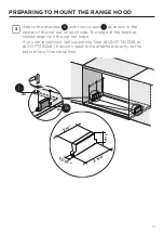
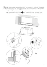
Attach the brackets
B
with two screws
I
as shown in the
center of the cut out on each side. The edge of the bracket
should align with the cut out edge.
If you are installing a Self supporting liner (#LINSPT301228 or
#LINSPT361228), brackets need to be attached directly to the
bottom lip of the metal liner.
3
B
=
=
4x
2x
I
Summary of Contents for INLT21SSV
Page 6: ...6 RANGE HOOD DIMENSIONS DRAFT 19 JUN 2020 14 46 21 28 35 21 28 35 DRAFT 19 JUN...
Page 7: ...7 INSTALLATION HEIGHT REQUIREMENTS MIN 24 OVER ELECTRIC MIN 30 OVER GAS Min 24 Min 30...
Page 9: ...9 A D E F Z B...
Page 28: ...28 120V 60Hz WIRING DIAGRAM...
Page 35: ...35 DIMENSIONS DE LA HOTTE DRAFT 19 JUN 2020 14 46 21 28 35 21 28 35 DRAFT 19 JUN...
Page 38: ...38 A D E F Z B...
Page 57: ...57 120V 60Hz SCH MA DE C BLAGE...
Page 64: ...64 DIMENSIONES DE LA CAMPANA EXTRACTORA DRAFT 19 JUN 2020 14 46 21 28 35 21 28 35 DRAFT 19 JUN...
Page 67: ...67 A D E F Z B...


