16
A4
´
;
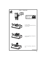
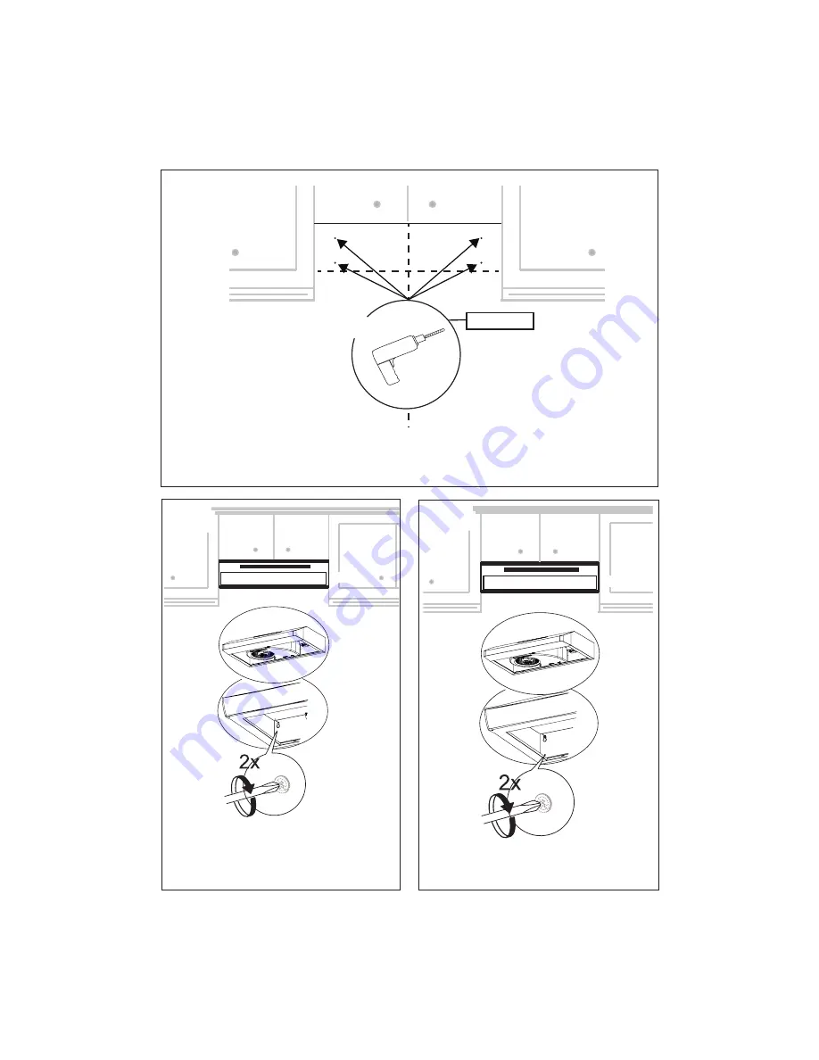
Drill directly into ø 3/16" holes at all the center points marked.
Insert the purchased wall plugs in the holes.
If fastener locations do not align with the studs, insert the purchased wall plugs in the holes.
A5
A6
In upper holes use two of the supplied screws to
secure the hood body to the wall.
Using two remaining screws anchor the hood in
lower holes as indicated.
Summary of Contents for LEVA24SS300-B
Page 5: ...5 RANGEHOOD DIMENSIONS Min 24 8 3...
Page 14: ...14 Installation for Mounting on the Wall Installation for Mounting to the cabinet 15 17...
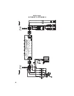
Page 20: ...20 U Wiring Diagram LEVT30SS400 B LEVT36SS400 B...
Page 26: ...26 DIMENSIONS DE LA HOTTE Min 24 8 3...
Page 35: ...35 15 17 Installation pour montage mural Installation pour montage l armoire...
Page 41: ...41 U Sch ma de c blage LEVT30SS400 B LEVT36SS400 B...
Page 44: ...991 0379 950_03 160115...

