background image

10

BEFORE INSTALLATION REMOVE SHIPPING 

MATERIALS

Remove the side packaging.

Remove the foam packaging and wood bar.

1

2

3

Ready for Installation.

Caution

: Do not 

pick up hood using 
the wood bar

Summary of Contents for LEVANTE 1

Page 1: ...N24SS300 LEVN30SS300 LEVN36SS300 Installation Instructions Use and Care Information Instructions d installation Utilisez et d entretien Instrucciones de instalaci n Informaci n de uso y cuidado LEVANT...

Page 2: ...or Horizontal Electrical Connection Knockout s 12 Ducted venting method options 14 Ducted 7 round outlet 15 Ducted 3 1 4 x 10 Rectangular Outlet on top 17 Ducted 3 1 4 x 10 Rectangular Outlet rear 18...

Page 3: ...ment is being called 4 You can fight the fire with your back to an exit Based on Kitchen Firesafety Tips published by NFPA WARNING TOREDUCETHERISKOFFIREORELECTRICSHOCK donotusethisfanwith any solid st...

Page 4: ...nd either through the wall or the roof The length of the ductwork and the number of elbows should be kept to a minimum to provide efficient performance The size of the ductwork should be uniform Do no...

Page 5: ...copper cable Allow some slack in the cable so the appliance can be moved if servicing is ever necessary A UL Listed 1 2 conduit connector must be provided at each end of the power supply cable at the...

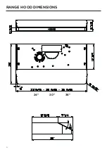
Page 6: ...6 RANGE HOOD DIMENSIONS 24 30 36...

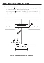
Page 7: ...7 MIN 24 OVER ELECTRIC MIN 30 OVER GAS Min 24 Min 30 INSTALLATION HEIGHT REQUIREMENTS...

Page 8: ...A Hood body Includes Controls Light Filters Blower 1 B Damper 3 1 4 x 10 1 C 7 Round Flange 1 D Grid Only for Canadian Market 1 REF PART E Pozi Screws 3 16 x 1 15 16 4 F Torx Screws 1 8 x 3 8 4 PARTS...

Page 9: ...per Wire connectors Power Supply Cable Drywall plugs or other suitable wall fasteners based on your installation Wall Cap Roof Cap Needs to be purchased separately TOOLS NEEDED TOOL Tape Measure Penci...

Page 10: ...10 BEFORE INSTALLATION REMOVE SHIPPING MATERIALS Remove the side packaging Remove the foam packaging and wood bar 1 2 3 Ready for Installation Caution Do not pick up hood using the wood bar...

Page 11: ...ured Install Grid D with the two screws removed from step 2 Screw the protection grid into the location shown in the picture below The correct location has a rectangular cut out to accommodate the gri...

Page 12: ...t the same time Remove the wiring box cover by unscrewing the 2 screws Preparing the hood for electrical knockouts 7 1 2 13 16 13 16 Created by GEN Lang EN Modif by As Approved b Approval da Doc statu...

Page 13: ...with a screwdriver or other tool During the installation thread Power Supply Cable through this hole 3 Top Hole Vertical Choose the top hole for the electric connection and break with a screwdriver o...

Page 14: ...UCTED VENTING METHOD OPTIONS DUCTED WITH 7 ROUND OUTLET Vertical Horizontal DUCTED WITH 3 1 4 X 10 RECTANGULAR OUTLET Vertical Horizontal 7 Rear Top 10 3 1 4 10 3 1 4 Rear Top Go to page 15 Go to page...

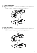
Page 15: ...ere indicated Remove both the rectangular and semicircle areas with metal shears Rear Top 7 Required 7 Round Damper purchase separately 1 Caution If an elbow is required do it as far away from the hoo...

Page 16: ...cure damper with foil duct tape Connect the 7 Round Metal Ductwork to the Roof or Wall Cap purchased separately and then attach ductwork Go to page 19 2 3 Torx Screwdriver NOTE The Flange must be moun...

Page 17: ...rectangular air outlet with two screws F Connect the metal ductwork to the Roof or Wall Cap purchased separately and then attach ductwork Rear Top Top 3 1 4 x 10 DUCTED 3 1 4 X 10 RECTANGULAR OUTLET O...

Page 18: ...ular air outlet with two screws F 1 2 Torx Screwdriver F Torx Screws 1 8 x 3 8 DUCTED 3 1 4 X 10 RECTANGULAR OUTLET REAR Caution If an elbow is required do it as far away from the hood s exhaust openi...

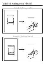
Page 19: ...19 CHOOSING THE MOUNTING METHOD Installation for Mounting on the Wall Installation for Mounting to the cabinet Page 20 Page 24...

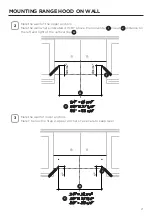
Page 20: ...t the center of the area in which the hood will be installed Draw a horizontal line I from where the bottom edge of hood will be located to a minimum of 24 above an electric cooking surface and 30 abo...

Page 21: ...4 15 16 24 A 21 3 8 30 A 27 3 8 36 A 33 3 8 A 24 A 21 3 8 30 A 27 3 8 36 A 33 3 8 A 4 15 16 1 1 4 15 16 24 A 21 3 8 30 A 27 3 8 36 A 33 3 8 A 24 A 21 3 8 30 A 27 3 8 36 A 33 3 8 A Mark the wall for l...

Page 22: ...nts marked in step 3 Iffastenerlocationsdonotalignwiththestuds insertthepurchasedwallplugsintheholes In upper holes use two of the supplied screws E to secure the hood body to the wall 5 Pozi Screwdri...

Page 23: ...23 Using two remaining screws E anchor the hood in lower holes as indicated 6 MOUNTING RANGE HOOD ON WALL Pozi Screwdriver E Pozi Screws 3 16 x 1 15 16...

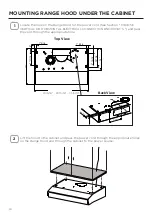
Page 24: ...710 R 0 7 1 2 13 16 13 16 Created b G Lang EN Modif by A Approved Approval Doc statu Dr 02 23 15 16 29 15 16 35 15 16 Locate the hole on the Range Hood for the power cord See Section CHOOSE VERTICAL O...

Page 25: ...to the cabinet Verify the measurement with the diagram on the previous page 3 Attach the Hood body with 4 screws E from the bottom available with the hood 4 E Pozi Screws 3 16 x 1 15 16 Pozi Screwdriv...

Page 26: ...onnections Attach the White lead of the Power Supply A to the White lead of the Range Hood D with a twist on type connector Attach the Black lead of the Power Supply to the Black lead of the Range Hoo...

Page 27: ...button to turn the light ON and press again to turn it OFF Blower On Off Button On Off button for the blower Press the button to turn the blower ON to speed one indicated by green LED and press again...

Page 28: ...as shown Insert the hood until the side supports snap into place Fasten using the 10 screws 12a provided Lock in position by tightening the screws Vf from underneath the hood Open the suction panel b...

Page 29: ...the picture Replace the bulb with a new one of the same type making sure that you insert the two pins properly into the housings on the lamp holder and twist to lock back in place Attention The bulbs...

Page 30: ...eated by Code BLU RED BLK GRY 1 2 3 4 5 6 BLK V1 MC F V2 ESZ 0 1 MOTOR Y G Y G 2 SPEED BLK BLK F 110 127V 60Hz WHT WHT N 3 I SPEED 0 1 LIGHT N L V4 L V3 WHT 1 2 3 4 5 6 WHT ORG VLT ORG BLU RED M8 4V B...

Page 31: ...ng from accident alteration misuse abuse fire flood acts of God improper installation installation not in accordance with electrical or plumbing codes or Faber documentation or use of products not app...

Page 32: ...lectrique d fon able verticale ou horizontale 43 Options avec ventilation canalis e 45 Canalisation conduit circulaire 7 46 Canalisation conduit rectangulaire 3 1 4 x 10 du dessus 48 Canalisation con...

Page 33: ...l pour teindre le feu Cela pourrait provoquer une violente explosion de vapeur d Utilisez un extincteur UNIQUEMENT si 1 Vous tes certain qu il s agit d un extincteur de classe ABC et que vous connaiss...

Page 34: ...xt rieur ou le plancher autour du clapet Iln estpasrecommand d utiliserdesconduitsflexibles Lesconduitsflexiblesprovoquent unecontre pressionetdelaturbulencequidiminuentgrandementl efficacit del appar...

Page 35: ...eu dans le c ble pour permettre le d placement de l appareil si des travaux d entretien s av raient n cessaires Un raccord de conduit homologu par l UL de 1 2 doit tre install aux deux extr mit s du c...

Page 36: ...re ou de mise la terre peut entra ner un choc lectrique Consultez un lectricien qualifi si vous n tes pas certain de la mise la terre de la hotte Le non respect des exigences de la fiche technique lec...

Page 37: ...37 DIMENSIONS DE LA HOTTE 24 30 36...

Page 38: ...38 Min 24 Min 30 HAUTEUR REQUISE POUR L INSTALLATION MIN 24 AU DESSUS D UNE SURFACE LECTRIQUE MIN 30 AU DESSUS D UNE SURFACE AU GAZ...

Page 39: ...hotte incluant commandes clairage filtres ventilateur 1 B Registre 3 1 4 x 10 1 C Bride circulaire 7 1 D Grille Canada uniquement 1 R F PI CE E Vis t te Pozidriv 3 16 x 1 15 16 4 F Vis t te toile 1 8...

Page 40: ...de fils C ble d alimentation lectrique Chevilles pour cloison s che ou autre syst me de fixation mural en fonction de votre installation Clapet de toiture clapet mural Doit tre achet s par ment OUTILS...

Page 41: ...EMBALLAGE AVANT DE PROC DER L INSTALLATION Enlevez les emballages lat raux Enlevez l emballage de mousse et la pi ce de bois 1 2 3 Vous tes pr t proc der l installation Attention Ne soulevez pas la h...

Page 42: ...llustr Installez la grille D avec les deux vis enlev es l tape 2 Vissez la grille de protection l endroit indiqu sur l illustration ci dessous L endroit correct pr sente une ouverture rectangulaire po...

Page 43: ...bas D vissez les 2 vis pour retirer le couvercle du bo tier de c blage Pr paration de la hotte pour le d foncement des orifices 7 1 2 13 16 13 16 Created by GEN Lang EN Modif by As Approved b Approval...

Page 44: ...autre outil Durant l installation faites passer le c ble d alimentation lectrique dans cet orifice 3 Orifice sup rieur vertical Choisissez l orifice du haut pour le branchement lectrique et brisez l...

Page 45: ...CANALIS E CANALISATION AVEC UN CONDUIT CIRCULAIRE DE 7 Vertical Horizontal CANALISATION AVEC CONDUIT RECTANGULAIRE 3 1 4 X 10 Vertical Horizontal 7 Arri re Haut 10 3 1 4 10 3 1 4 Arri re Haut Passez l...

Page 46: ...iqu s Retirez les zones rectangulaires et le demi cercle l aide de cisailles m taux Arri re Haut 7 Requis registre circulaire 7 achet s par ment 1 Attention Si vous devez installer un coude placez le...

Page 47: ...ruban m tallique pour canalisation Raccordez le conduit m tallique circulaire de 7 au clapet de toiture ou au clapet mural achet s par ment puis raccordez les conduits Passez la page 50 2 3 Tournevis...

Page 48: ...aide de deux vis F Raccordez le conduit m tallique au clapet de toiture ou au clapet mural achet s par ment puis raccordez les conduits Arri re Haut Haut 3 1 4 x 10 CANALISATION CONDUIT RECTANGULAIRE...

Page 49: ...e l aide de deux vis F 1 2 Tournevis toile F Vis t te toile 1 8 x 3 8 CANALISATION CONDUIT RECTANGULAIRE 3 1 4 X 10 L ARRI RE Attention Si vous devez installer un coude placez le le plus loin possible...

Page 50: ...50 CHOISIR LA M THODE DE MONTAGE Installation pour montage mural Installation pour montage l armoire Page 20 Page 24...

Page 51: ...a hotte sera install e Tracez une ligne horizontale I l endroit correspondant au bas de la hotte cet emplacement doit se trouver une distance d au moins 24 de la surface de cuisson si elle est lectriq...

Page 52: ...6 24 A 21 3 8 30 A 27 3 8 36 A 33 3 8 A 24 A 21 3 8 30 A 27 3 8 36 A 33 3 8 A 4 15 16 1 1 4 15 16 24 A 21 3 8 30 A 27 3 8 36 A 33 3 8 A 24 A 21 3 8 30 A 27 3 8 36 A 33 3 8 A Marquez l emplacement des...

Page 53: ...emplacement des fixations n est pas align avec les chevrons ins rez les chevilles achet es dans les trous Dans les trous du haut utilisez deux des vis fournies E pour fixer le b ti de la hotte au mur...

Page 54: ...54 Utilisez les deux vis restantes E dans les trous du bas pour ancrer la hotte au mur 6 MONTAGE DE LA HOTTE AU MUR Tournevis Pozidriv E Vis t te Pozidriv 3 16 x 1 15 16...

Page 55: ...1 2 13 16 13 16 Created b G Lang EN Modif by A Approved Approval Doc statu Dr 02 23 15 16 29 15 16 35 15 16 Rep rez le trou de la hotte pour le cordon d alimentation consultez la section CHOISIR L ENT...

Page 56: ...hotte l armoire V rifiez les mesures l aide du diagramme de la page pr c dente 3 Fixez le b ti de la hotte l aide des 4 vis E du bas fournies avec la hotte 4 E Vis t te Pozidriv 3 16 x 1 15 16 Tourne...

Page 57: ...exion Branchez le fil blanc de l alimentation A au fil blanc de la hotte D l aide d un connecteur verrouill par rotation Branchez le fil noir de l alimentation au fil noir de la hotte B l aide d un co...

Page 58: ...ouvelle fois pour l teindre Interrupteur du ventilateur Interrupteur Marche Arr t pour le ventilateur Appuyez sur le bouton pour mettre le ventilateur en marche la premi re vitesse signal e par le t m...

Page 59: ...snap into place Fasten using the 10 screws 12a provided Lock in position by tightening the screws Vf from underneath the hood Open the suction panel by turning the specific knob Disconnect the panel f...

Page 60: ...cez l ampoule avec une autre du m me type en vous assurant d ins rer correctement les deux connecteurs dans leur logement puis tournez pour la verrouiller en place noter Les ampoules pourraient tre ch...

Page 61: ...reated by Code BLU RED BLK GRY 1 2 3 4 5 6 BLK V1 MC F V2 ESZ 0 1 MOTOR Y G Y G 2 SPEED BLK BLK F 110 127V 60Hz WHT WHT N 3 I SPEED 0 1 LIGHT N L V4 L V3 WHT 1 2 3 4 5 6 WHT ORG VLT ORG BLU RED M8 4V...

Page 62: ...ng from accident alteration misuse abuse fire flood acts of God improper installation installation not in accordance with electrical or plumbing codes or Faber documentation or use of products not app...

Page 63: ...horizontales 74 Opciones de m todo de ventilaci n canalizada 76 Canalizada salida redonda de 7 77 Canalizada salida rectangular de 3 1 4 x 10 en la parte superior 79 Canalizada salida rectangular de...

Page 64: ...ENTE si 1 Usted sabe que tiene un extintor Clase ABC y ya sabe c mo operarlo 2 El incendio es peque o y est contenido en el rea donde comenz 3 Se llama al departamento de bomberos 4 Puede luchar contr...

Page 65: ...ura del piso alrededor de la tapa NOserecomiendanconductosflexibles Losconductosflexiblescreanunacontrapresi n y turbulencias de aire que reducen en gran medida el rendimiento Aseg rese de que haya es...

Page 66: ...ational Fire Protection Association Batterymarch Park Quincy Massachusetts 02269 Este electrodom stico debe conectarse directamente a la desconexi n por fusible o disyuntor a trav s de un cable flexib...

Page 67: ...e tierra Si la tuber a de agua fr a est interrumpida por juntas de pl stico de materiales no met licos u otros materiales NO la utilice para conexi n a tierra NO conecte a tierra a una tuber a de gas...

Page 68: ...68 DIMENSIONES DE LA CAMPANA EXTRACTORA 24 30 36...

Page 69: ...69 Min 24 Min 30 REQUISITOS DE ALTURA DE INSTALACI N M N 24 SOBRE PLACA EL CTRICA MIN 30 SOBRE PLACA DE GAS...

Page 70: ...mpana Incluye controles luz filtros ventilador 1 B Registro 3 1 4 x 10 1 C Brida redonda de 7 1 D Rejilla solo para el mercado canadiense 1 REF PIEZA E Tornillos Pozi 3 16 x 1 15 16 4 F Tornillos Torx...

Page 71: ...cable Cable de suministro de energ a Tacos para pared de yeso u otros sujetadores de pared adecuados seg n su instalaci n La tapa de la pared del techo deben comprarse por separado HERRAMIENTAS NECESA...

Page 72: ...LA INSTALACI N RETIRE LOS MATERIALES DE ENV O Retire el embalaje lateral Retire el embalaje de espuma y la barra de madera 1 2 3 Lista para la instalaci n Precauci n No levante la campana con la barr...

Page 73: ...s dos tornillos retirados desde el paso 2 Atornille la rejilla de protecci n en la ubicaci n que se muestra en la imagen a continuaci n La ubicaci n correcta tiene un corte rectangular para acomodar l...

Page 74: ...o Retire la cubierta de la caja de cableado desatornillando los 2 tornillos Preparaci n de la campana para paneles de conexi n el ctricos 7 1 2 13 16 13 16 Created by GEN Lang EN Modif by As Approved...

Page 75: ...r u otra herramienta Durante la instalaci n pase el cable de alimentaci n a trav s de este orificio 3 Agujero superior vertical Elija el orificio superior para la conexi n el ctrica y r mpalo con un d...

Page 76: ...IZADA CANALIZADA CON SALIDA REDONDA DE 7 Vertical Horizontal CANALIZADA CON SALIDA RECTANGULAR DE 3 1 4 X 10 Vertical Horizontal 7 Parte trasera Parte superior 10 3 1 4 10 3 1 4 Parte trasera Parte su...

Page 77: ...Retire las reas rectangulares y de semic rculo con tijeras de metal Parte trasera Parte superior 7 Necesario Registro redondo de 7 se compre por separado 1 Precauci n Si se requiere un codo h galo lo...

Page 78: ...on cinta adhesiva de aluminio Conecte el conducto de metal redondo de 7 al techo o la tapa de pared que se compra por separado y luego conecte el conducto Ir a la p gina 81 2 3 Destornillador Torx NOT...

Page 79: ...on dos tornillos F Conecte los conductos met licos al techo o la tapa de pared que se compran por separado y luego conecte los conductos Parte trasera Parte superior Parte superior 3 1 4 x 10 CANALIZA...

Page 80: ...da con dos tornillos F 1 2 Destornillador Torx F Tornillos Torx 1 8 x 3 8 CANALIZADA SALIDA RECTANGULAR DE 3 1 4 X 10 EN LA PARTE TRASERA Precauci n Si se requiere un codo h galo lo m s lejos posible...

Page 81: ...81 ELECCI N DEL M TODO DE MONTAJE Instalaci n para montaje en la pared Instalaci n para montaje en gabinete P gina 20 P gina 24...

Page 82: ...la zona en la que se instalar la campana Trace una l nea horizontal I desde donde se ubicar el borde inferior de la campana a un m nimo de 24 sobre una superficie de cocci n el ctrica y 30 sobre una s...

Page 83: ...3 8 30 A 27 3 8 36 A 33 3 8 A 24 A 21 3 8 30 A 27 3 8 36 A 33 3 8 A 4 15 16 1 1 4 15 16 24 A 21 3 8 30 A 27 3 8 36 A 33 3 8 A 24 A 21 3 8 30 A 27 3 8 36 A 33 3 8 A Marque la pared para los anclajes i...

Page 84: ...de los sujetadores no se alinean con los postes inserte los tacos de pared comprados en los agujeros En los orificios superiores use dos de los tornillos suministrados E para asegurar el cuerpo de la...

Page 85: ...85 Usando dos tornillos restantes E ancle la campana en los agujeros inferiores como se indica 6 MONTAJE DE LA CAMPANA EXTRACTORA EN LA PARED Destornillador Pozi E Tornillos Pozi 3 16 x 1 15 16...

Page 86: ...b G Lang EN Modif by A Approved Approval Doc statu Dr 02 23 15 16 29 15 16 35 15 16 Localice el agujero en la campana del campo de tiro para el cable de alimentaci n Vea la secci n ELIJA PANELES DE CO...

Page 87: ...te Compruebe la medida con el diagrama de la p gina anterior 3 Fije el cuerpo de la campana con 4 tornillos E desde abajo disponible con la campana 4 E Tornillos Pozi 3 16 x 1 15 16 Destornillador Poz...

Page 88: ...cable blanco de la fuente de alimentaci n A al cable blanco de campana extractora D con un conector de cable tipo twist on Conecte el cable negro de la fuente de alimentaci n al cable negro de la cam...

Page 89: ...z y presi nelo nuevamente para apagarla Interruptor de encendido apagado del ventilador Bot n de encendido apagado para el soplador Presione el bot n para encender el ventilador a la velocidad uno ind...

Page 90: ...upports snap into place Fasten using the 10 screws 12a provided Lock in position by tightening the screws Vf from underneath the hood Open the suction panel by turning the specific knob Disconnect the...

Page 91: ...a a colocar la bombilla con una nueva del mismo tipo asegur ndose de que inserta los dos pines correctamente en las carcasas del soporte de la l mpara y g rela para volverla a encajar en su lugar Aten...

Page 92: ...Created by Code BLU RED BLK GRY 1 2 3 4 5 6 BLK V1 MC F V2 ESZ 0 1 MOTOR Y G Y G 2 SPEED BLK BLK F 110 127V 60Hz WHT WHT N 3 I SPEED 0 1 LIGHT N L V4 L V3 WHT 1 2 3 4 5 6 WHT ORG VLT ORG BLU RED M8 4...

Page 93: ...co distinto al normal 4 Da os resultantes de accidente alteraci n mal uso abuso incendio inundaci n eventos naturales instala ci n incorrecta instalaci n no conforme a los c digos el ctricos o de plom...

Page 94: ...94...

Page 95: ...95...

Page 96: ...991 0602 698_01 200120 D00000525_00...

Reviews: