background image

42

REQUISITOS ELÉCTRICOS

$MTMBHQBTHSNRDO@Q@CNCDETRHAKDCD@LODQHNRRDQDPTHDQDTMRTLHMHRSQNDKġBSQHBN

de solo 120 voltios, 60 Hz CA.  Se recomienda un fusible o disyuntor de retardo.  El 

ETRHAKDCDADCHLDMRHNM@QRDRDFŕMKNRBłCHFNRKNB@KDRCD@BTDQCNBNMK@BK@RHjB@BHłM

DKġBSQHB@CDDRS@TMHC@CS@KBNLNRDDRODBHjB@DMK@OK@B@CDRDQHDCDB@Q@BSDQİRSHB@R

situada en el interior de la unidad cerca del compartimiento de cableado de campo. 

INSTALACIÓN ELÉCTRICA CON CAJA DE CABLEADO

ESTA UNIDAD DEBE CONECTARSE SOLAMENTE CON ALAMBRE DE COBRE.  Los 

S@L@ľNRCDKNRB@AKDRCDADMBTLOKHQBNMKNRQDPTHRHSNRCDK"łCHFN$KġBSQHBN-@BHNM@K

 -2(-%/ ŕKSHL@DCHBHłMXSNCNRKNRBłCHFNRXNQCDM@MY@RKNB@KDR$KS@L@ľN

CDKB@AKDXK@RBNMDWHNMDRCDADM@ITRS@QRD@K@RDRODBHjB@BHNMDRCDK@O@Q@SN2D

pueden obtener copias de la norma antes mencionada en: 


National Fire Protection Association


Batterymarch Park


Quincy, Massachusetts  02269

Este aparato debe conectarse directamente a la desconexión de fusible (o disyuntor) a 

SQ@UġRCDTMB@AKDCDBNAQDkDWHAKDAKHMC@CNNMNLDSđKHBN#DIDTMONBNCDGNKFTQ@

en el cable para que el aparato pueda moverse si es necesario realizar algún tipo de 
mantenimiento.  En cada extremo del cable de alimentación (en el aparato y en la caja 

CDDLO@KLDRCDADDMBNMSQ@QRDTMBNMDBSNQCDBNMCTBSNCDŭBDQSHjB@CN4+

 KG@BDQK@BNMDWHłMDKġBSQHB@QD@KHBDTM@FTIDQNCDŭDMK@O@QDC4M@FTIDQN

BNQS@CN@SQ@UġRCDK@L@CDQ@CDADRDQKHI@CNG@RS@PTDDRSġKHRN4M@FTIDQN@SQ@UġR

del metal debe tener un ojal. 

q$RS@B@LO@M@QDPTHDQDBNMDWHłMDKġBSQHB@CDSHDQQ@

• Si la tubería de agua fría está interrumpida por juntas de plástico, de materiales no 

metálicos u otros materiales, NO la utilice para conexión a tierra.

• NO conecte a tierra una tubería de gas.
• NO coloque un fusible en el circuito de neutro o tierra.  Un fusible en el neutro o circuito 

CDOTDRS@@SHDQQ@ONCQİ@C@QKTF@Q@TM@CDRB@QF@DKġBSQHB@

q"NMRTKSDBNMTMDKDBSQHBHRS@B@KHjB@CNRHSHDMDCTC@R@BDQB@CDRHK@B@LO@M@DRSđ

correctamente conectada a tierra. 

q$KHMBTLOKHLHDMSNCDKNRQDPTHRHSNRDKġBSQHBNROTDCDOQNUNB@QTMHMBDMCHN

   ADVERTENCIA

!

Summary of Contents for Levante 2 Plus

Page 1: ...LEVL30SS400 LEVL36SS400 Installation Instructions Use and Care Information Instructions d installation Utilisez et d entretien Instrucciones de instalaci n Informaci n de uso y cuidado...

Page 2: ...THE RISK OF FIRE OR ELECTRIC SHOCK do not use this fan with any solid state speed control device WARNING TO REDUCE THE RISK OF FIRE ELECTRICAL SHOCK OR INJURY TO PER SONS OBSERVE THE FOLLOWING 1 Use...

Page 3: ...jQD WARNING Cold Weather installations M CCHSHNM K A BJ CQ ES C LODQ RGNTKC AD HMRS KKDC SN LHMHLHYD A BJV QC BNKC HQ kNV MC MNM metallic thermal break should be installed to minimize conduction of ou...

Page 4: ...should be connected directly to the fused disconnect or circuit breaker through kDWHAKD QLNQDC NQ MNMLDS KKHB RGD SGDC BNOODQ B AKD KKNV RNLD RK BJ HM SGD B AKD RN SGD OOKH MBD B M AD LNUDC HE RDQUHBH...

Page 5: ...5 RANGEHOOD DIMENSIONS Min 24 Max 30...

Page 6: ...d locally 12C Wall Mount Screws may work as fasteners for this W SH RI LQVWDOO LI QRW WKHQ IRXU DW KHDG ZRRG VFUHZV ZLOO DOVR QHHG WR EH SXUFKDVHG ORFDOO WR FRPSOHWH WKLV type of install MAIN PARTS Co...

Page 7: ...These Shipping Materials Remove the side packaging Remove the wood shipping by unscrew the 4 screws Ready for Installation Remove the internal block as VKRZQ LQ D JXUH to the right Remove the block as...

Page 8: ...T 5HPRYH WKH OWHUV RQH DW D WLPH E pushing them towards the back of the group and pulling down at the same time Install the Grid 13 with 2 screws removed previously as shown in the picture 13 5HPRYH W...

Page 9: ...at the same time Remove the wiring box cover by unscrewing the 2 screws Choose the rear hole or top hole for the electric connection and break with a screwdriver or other tool During the installation...

Page 10: ...10 7 10 3 1 4 10 3 1 4 Ducting Methods Ducted with 7 Round Outlet Ducted with 3 1 4 x 10 Rectangular Outlet Rear Top Rear Top...

Page 11: ...indicated Remove both the angular and semicircle areas with metal shears Install the Flange with Flange transition screws 12c Install 7 Round Damper purchased sepa rately Rear Top 7 Required 7 Round...

Page 12: ...0 Choose the rectangular upper air outlet or rectangular rear air outlet and cut where indicated QVWDOO WKH LQFOXGHG UHFWDQJXODU DLU RXWOHW ZLWK WZR DQJH WUDQVLWLRQ VFUHZV Rear Rear Top Rear Top 3 1 4...

Page 13: ...13 Installation for Mounting on the Wall Installation for Mounting to the cabinet 14 16...

Page 14: ...edge of the hood will be located as indicated LQ WKH JXUH WKDW LV D PLQLPXP RI above cooking surface 4 15 16 4 15 16 24 A 21 3 8 30 A 27 3 8 36 A 33 3 8 A 1 1 24 A 21 3 8 30 A 27 3 8 36 A 33 3 8 A A2...

Page 15: ...hased wall plugs in the holes If fastener locations do not align with the studs insert the purchased wall plugs in the holes A5 A6 In upper holes use two of the supplied screws to secure the hood body...

Page 16: ...r to the Cabinet Mark the KROHV IRU LQJ verifying the measures with the diagram Lift the hood to the cabinet Fix the Hood Body with 4 screws from the bottom 20 24 30 36 12 7 2 13 16 10 1 2 1 5 16 1 5...

Page 17: ...OG ZLULQJ FRPSDUWPHQW FRYHU DQG WKH JUHDVH OWHUV Hood wiring USE AND CARE INFORMATION T1 Hood ON OFF button The hood can be turned on by pressing any of the fan settings T2 Fan Settings Buttons Low Sp...

Page 18: ...aveabsolutelyno HIIHFW RQ LWV HI FLHQF Replace taking care to ensure that the handle faces forward OHDQLQJ LQ GLVKZDVKHU PD GXOO WKH QLVK RI WKH PHWDO JUHDVH OWHU Replacing the light unit 5 W LED Type...

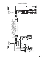
Page 19: ...19 Wiring Diagram U...

Page 20: ...on misuse abuse fire flood acts of God improper installation installation not in accordance with electrical or plumbing codes or Faber documentation or use of products not approved by Faber 5 Replacem...

Page 21: ...K TW S SR 4MHR AVERTISSEMENT POUR R DUIRE LE RISQUE D INCENDIE OU DE CHOC LECTRIQUE n utilisez jamaisceventilateurenassociationavecundispositifder glagedevitesse semi conducteurs AVERTISSEMENT POUR R...

Page 22: ...KD L SGNCD CD UDMSHK SHNM DRS LHDTW C OS D UNSQD OOKHB SHNM DR BNMCTHSR ODTUDMS passer par le mur ou le toit NTQ F Q MSHQ TMD LDHKKDTQD DEjB BHS K KNMFTDTQ CDR BNMCTHSR DS KD MNLAQD CD BNTCDR CNHUDMS...

Page 23: ...NT T CHRINMBSDTQ O Q TM B AKD kDWHAKD CD BTHUQD UDB AKHMC FD NT F HMD MNM L S KKHPTD HRRDY TM ODT CD IDT C MR KD B AKD ONTQ ODQLDSSQD KD C OK BDLDMS CD Ke OO QDHK RH CDR SQ U TW CeDMSQDSHDM Re U Q HDM...

Page 24: ...24 DIMENSIONS DE LA HOTTE Min 24 MAx 30...

Page 25: ...2 x 12 longueur approximative Les vis de montage PXUDO SHXYHQW V DYpUHU DGpTXDWHV HQ JXLVH GH DWLRQ SRXU FH W SH G LQVWDOODWLRQ DQV OH FDV FRQWUDLUH il est galement n cessaire de se procurer sur place...

Page 26: ...proc der l installation Enlevez les emballages lat raux Enlevez le cadre de bois en d vissant les 4 vis Vous tes pr t proc der l installation D placez le bloc interne comme indiqu dans une JXUH j GURL...

Page 27: ...ENT 5HWLUH OHV OWUHV XQ j XQ HQ OHV SRXV sant simultan ment vers l arri re du groupe et en les tirant vers le bas Retirez les 2 vis d j pos es Installez la grille 13 l aide de 2 vis enlev es pr c demm...

Page 28: ...groupe et en les tirant vers le bas D vissez les 2 vis pour re tirer le couvercle du bo tier de c blage KRLVLVVH VL YRXV XWLOLVHUH O RUL FH DUULqUH RX O RUL FH VXSpULHXU SRXU OH EUDQFKHPHQW pOHFWULTX...

Page 29: ...29 7 10 3 1 4 10 3 1 4 M KHR SHNM UDB TM BNMCTHS BHQBTK HQD CD Canalisation avec conduit rectangulaire 3 W Arri re Haut M thodes de canalisation Arri re Haut...

Page 30: ...rculaire 7 se procurer sur place Coupez aux endroits indiqu s Retirez les zones angulaires et le demi cercle l aide de cisailles m taux QVWDOOH OH DVTXH j O DLGH GHV YLV SRXU UDF FRUG GH WUDQVLWLRQ GX...

Page 31: ...n 3 1 4 W Arri re Haut Arri re Choisissez la sortie d air rectangulaire sup rieur ou arri re et coupez l endroit indiqu Arri re Haut QVWDOOH OD VRUWLH G DLU UHFWDQJXODLUH IRXUQLH j O DLGH GH GHX YLV S...

Page 32: ...32 33 35 Installation pour montage mural Installation pour montage l armoire...

Page 33: ...ra install e Tracez une ligne horizontale l endroit correspon dant au bas de la hotte comme repr sent dans l illustration Cet emplacement doit se trouver au moins 24 30 de la surface de cuisson Tracez...

Page 34: ...s dans les trous 6L OHPSODFHPHQW GHV DWLRQV QHVW SDV DOLJQp DYHF OHV FKHYURQV LQVpUH OHV FKHYLOOHV DFKHWpHV GDQV OHV WURXV Dans les trous sup rieurs utilisez deux des vis IRXUQLHV SRXU HU OH EkWL GH O...

Page 35: ...les rep res pour l installation HQ YpUL DQW les mesures l aide du diagramme Soulevez la hotte jusqu l armoire Fixez le b ti de la hotte par le des sous l aide des 4 vis 20 24 30 36 12 7 2 13 16 10 1...

Page 36: ...RMATIONS POUR L UTILISATION ET L ENTRETIEN Pour de meilleurs r sultats FWLYH OD KRWWH TXHOTXHV PLQXWHV DYDQW GH FRPPHQFHU j FXLVLQHU SRXU FUpHU XQ X G DLU DGpTXDW DLV VH OD KRWWH IRQFWLRQQHU TXHOTXHV...

Page 37: ...un changement GH OD FRXOHXU j OD VXUIDFH GX OWUH DX O GX WHPSV QD DXFXQ LPSDFW VXU VRQ HI FDFLWp Remettez le en place en vous assurant que la poign e se trouve vers l avant H ODYH YDLVVHOOH SRXUUDLW W...

Page 38: ...38 Sch ma de c blage U...

Page 39: ...ent d une modification de l utilisation incorrecte ou abusive d un incendie d une inondation d un cas de force majeure d une installation inad quate d une installation non conforme aux codes en mati r...

Page 40: ...con la espalda dirigida hacia una salida Basado en Consejos para luchas contra los incendios en las cocinas publicado por NFPA ADVERTENCIA PARAREDUCIRELRIESGODEDESCARGASEL CTRICASOINCEN DIOS no use es...

Page 41: ...D EQ N G BH SQ R X RD CDAD HMRS K Q TM CHRXTMSNQ S QLHBN MN LDS KHB O Q LHMHLHY Q K BNMCTBBH M CD K R temperaturas exteriores como parte del sistema de ventilaci n El registro debe estar en DK K CN CD...

Page 42: ...irectamente a la desconexi n de fusible o disyuntor a SQ U R CD TM B AKD CD BNAQD kDWHAKD AKHMC CN N MN LDS KHBN DID TM ONBN CD GNKFTQ en el cable para que el aparato pueda moverse si es necesario rea...

Page 43: ...43 DIMENSIONES DE LA CAMPANA Min 24 Max 30...

Page 44: ...te Los tornillos GH PRQWDMH HQ SDUHG SXHGHQ IXQFLRQDU FRPR VXMHWDGRUHV SDUD HVWH WLSR GH LQVWDODFLyQ GH QR VHU DVt WDP ELpQ VH QHFHVLWDUi DGTXLULU FXDWUR WRUQLOORV GH PDGHUD GH FDEH D SODQD SDUD FRPSO...

Page 45: ...sportaci n Retire el embalaje lateral Retire el transporte de mad era para esto desenrosque los 4 tornillos LVWR SDUD OD LQVWDODFLyQ Retire el bloque interno como se muestra en XQD JXUD D OD derecha R...

Page 46: ...ORV OWURV XQR D OD YH HPSXMiQ dolos hacia la parte posterior del grupo y tirando hacia abajo al mismo tiempo Instale la rejilla 13 con los 2 tornillos H WUDtGRV DQWHULRUPHQWH FRPR VH PXHV tra en la im...

Page 47: ...a de la caja de cableado desenroscando los 2 tornillos OLMD HO DJXMHUR WUDVHUR R DJXMHUR VXSHULRU SDUD OD FRQH LyQ HOpFWULFD URPSD FRQ XQ GHVWRUQLOODGRU X RWUD herramienta XUDQWH OD LQVWDODFLyQ SDVH H...

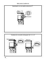
Page 48: ...48 7 10 3 1 4 10 3 1 4 M todos de canalizaci n Canalizaci n con una salida redonda de 7 Canalizaci n con salida rectangular de 3 1 4 x 10 Posterior Parte superior Posterior Parte superior...

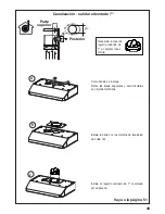
Page 49: ...as angulares y semicirculares con tijeras met licas QVWDOH OD EULGD FRQ ORV WRUQLOORV GH WUDQVLFLyQ de brida 12c Instale el registro redondo de 7 comprado por separado Posterior Parte superior 7 Neces...

Page 50: ...r rectangular o la salida de aire posterior rectangular y corte donde se indique QVWDOH OD VDOLGD GH DLUH UHFWDQJXODU LQFOXLGD FRQ GRV WRUQLOORV GH WUDQVLFLyQ GH EULGD Posterior Posterior Parte superi...

Page 51: ...51 Instalaci n para montaje en la pared Instalaci n para montaje en el gabinete 52 54...

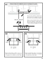
Page 52: ...se ubicar como se LQGLFD HQ OD JXUD TXH HV XQ PtQLPR GH SRU HQFLPD GH OD VXSHU FLH GH FRFFLyQ 4 15 16 4 15 16 24 A 21 3 8 30 A 27 3 8 36 A 33 3 8 A 1 1 24 A 21 3 8 30 A 27 3 8 36 A 33 3 8 A A2 A3 Mar...

Page 53: ...iones de los sujetadores no se alinean con los pernos inserte los tapones de pared adquiridos HQ ORV RUL FLRV A5 A6 Q ORV RUL FLRV VXSHULRUHV XWLOLFH GRV GH ORV WRUQLOORV VXPLQLVWUDGRV SDUD MDU HO FXH...

Page 54: ...ue los agujeros para OD MDFLyQ comprobando las medidas con el dia grama Levante la campana hasta el gabi nete Fije el cuerpo de la campana con 4 tornillos desde la parte inferior 20 24 30 36 12 7 2 13...

Page 55: ...INFORMACI N DE USO Y CUIDADO T1 Bot n de apagado del ventilador Apaga el ventilador El ventilador puede ser operado pulsando cualquiera de los botones de ajuste del ventilador T2 Botones de ajuste de...

Page 56: ...GUi QLQJ Q HIHFWR VREUH VX H FLHQFLD Reemplace asegur ndose de que el asa est orientada hacia adelante La limpieza en el lavavajillas puede estropear HO DFDEDGR GHO OWUR GH JUDVD PHWiOLFR Sustituci n...

Page 57: ...57 Diagrama de cableado U...

Page 58: ...stico distinto al normal DxRV UHVXOWDQWHV GH DFFLGHQWH DOWHUDFLyQ PDO XVR DEXVR LQFHQGLR LQXQGDFLyQ HYHQWRV QDWXUDOHV LQVWDOD FLyQ LQFRUUHFWD LQVWDODFLyQ QR FRQIRUPH D ORV FyGLJRV HOpFWULFRV R GH SORP...

Page 59: ...ina se utiliza al mismo tiempo que los aparatos que consumen gas u otros combustibles Detallar acerca del m todo y frecuencia de limpieza Existe el riesgo de fuego si la limpieza no se realiza de acue...

Page 60: ...mpara todas las piezas y componentes del producto e incluye la mano de obra as como el reemplazo de cualquier pieza o componente defectuoso sin costo adicional para el consumidor 2D HMBKTXDM S LAH M K...

Page 61: ...61...

Page 62: ...62...

Page 63: ...63...

Page 64: ...991 0524 145_01 171012 D0004047_00...

Reviews: