3
ALL WALL AND FLOOR OPENINGS WHERE THE RANGEHOOD IS INSTALLED MUST
BE SEALED.
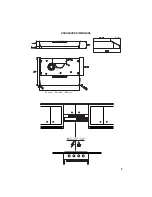
This rangehood requires at least 24" of clearance
between the bottom of the rangehood
and the cooking surface or countertop. This hood has been approved by UL at this distance from
the cooktop.
This minimum clearance may be higher depending on local building codes. For gas cooktops and
combination ranges, a minimum of 30" is recommended and may be required.
The maximum depth of overhead cabinets is 13". Overhead cabinets on both sides of this unit
must be a minimum of 18" above the cooking surface or countertop. Consult the cooktop or range
installation instructions given by the manufacturer before making any cutouts.
MOBILE HOME INSTALLATION The installation of this rangehood must conform to the Manufactured
Home Construction and Safety Standards, Title 24 CFR, Part 3280 (formerly Federal Standard
for Mobile Home Construction and Safety, Title 24, HUD, Part 280). See Electrical Requirements.
• Venting system MUST terminate outside the home.
•
DO NOT
terminate the ductwork in an attic or other enclosed space.
•
DO NOT
use 4" laundry-type wall caps.
• Flexible-type ductwork is not recommended.
•
DO NOT
NARSQTBSSGDkNVNEBNLATRSHNM@MCUDMSHK@SHNM@HQ
q%@HKTQDSNENKKNVUDMSHMFQDPTHQDLDMSRL@XQDRTKSHM@jQD
WARNING
!
Cold Weather installations
M@CCHSHNM@KA@BJCQ@ESC@LODQRGNTKCADHMRS@KKDCSNLHMHLHYDA@BJV@QCBNKC@HQkNV@MC@MNM
-
metallic thermal break should be installed to minimize conduction of outside temperatures as part of
the vent system. The damper should be on the cold air side of the thermal break. The break should
be as close as possible to where the vent system enters the heated portion of the house.
VENTING REQUIREMENTS
Determine which venting method is best for your application. Ductwork can extend either through the
wall or the roof.
3GDKDMFSGNESGDCTBSVNQJ@MCSGDMTLADQNEDKANVRRGNTKCADJDOSSN@LHMHLTLSNOQNUHCDDEjBHDMS
performance. The size of the ductwork should be uniform. Do not install two elbows together. Use duct
S@ODSNRD@K@KKINHMSRHMSGDCTBSVNQJRXRSDL4RDB@TKJHMFSNRD@KDWSDQHNQV@KKNQkNNQNODMHMF@QNTMC
the cap.
Flexible ductwork is not recommended. Flexible ductwork creates back pressure and air turbulence that
greatly reduces performance.
,@JDRTQDSGDQDHROQNODQBKD@Q@MBDVHSGHMSGDV@KKNQkNNQENQDWG@TRSCTBSADENQDL@JHMFBTSNTSR#N
not cut a joist or stud unless absolutely necessary. If a joist or stud must be cut, then a supporting frame
must be constructed.
WARNING - To Reduce The Risk Of Fire, Use Only Metal Ductwork.
" 43(.-3NQDCTBDQHRJNEkQD@MCSNOQNODQKXDWG@TRS@HQADRTQDSNCTBS@HQNTSRHCDm#N
not vent exhaust air into spaces within walls or ceilings or into attics, crawl spaces, or garages.
Summary of Contents for Levante I
Page 5: ...5 RANGEHOOD DIMENSIONS Min 24 30 7 1 4 3 23 15 16 29 15 16 35 15 16 ...
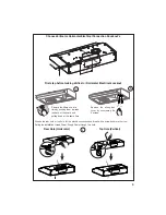
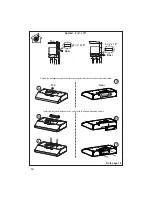
Page 14: ...14 Installation for Mounting on the Wall Installation for Mounting to the cabinet 15 17 ...
Page 20: ...20 Wiring Diagram LEVT30SS400 B LEVT36SS400 B ...
Page 26: ...26 DIMENSIONS DE LA HOTTE 7 1 4 3 23 15 16 29 15 16 35 15 16 Min 24 30 ...
Page 35: ...35 36 38 Installation pour montage mural Installation pour montage à l armoire ...
Page 41: ...41 Schéma de câblage LEVT30SS400 B LEVT36SS400 B ...
Page 47: ...47 DIMENSIONES DE LA CAMPANA 7 1 4 3 23 15 16 29 15 16 35 15 16 Min 24 30 ...
Page 56: ...56 Instalación para montaje en la pared Instalación para montaje en el gabinete 57 59 ...
Page 62: ...62 Diagrama de cableado LEVT30SS400 B LEVT36SS400 B ...
Page 67: ...67 ...
Page 68: ... B B ...

