background image


GR 

4

47 

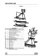
ΧΑΡΑΚΤΗΡΙΣΤΙΚΑ


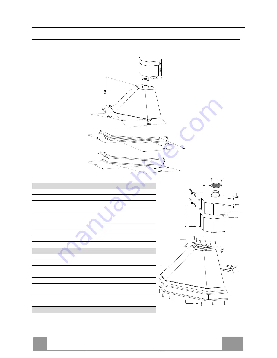
Διαστάσεις


Cornice piastrellabile


Εξαρτή

µ

ατα


Αναφ

.  

Ποσ

Εξαρτή

µ

ατα


της


συσκευής


 1 


Σώ

µ

α


απορροφητήρα

 µ

ε

Χειριστήρια

Φωτισ

µ

ό

Σύ


στη

µ

α


φτερωτής

Φίλτρα


2

 1 


Τηλεσκοπική


κα

µ

ινάδα


αποτελού

µ

ενη


από

2.1


Πάνω


κα

µ

ινάδα


2.2 

 1 

Κάτω


κα

µ

ινάδα


8

 1 

Ρυθμιζόμενη


γρίλια


Φ

 125 mm 

 1 

Φλάντζα


συστολής


Φ

 150-120 mm 

10

 1 

Κορνίζα


ραφιού

 (

προαιρετική

20

 1 

Ξύλινο


προφίλ

 (

προαιρετικό

30

 1 

Κάτω


τάπα


γωνίας


Αναφ

.  

Ποσ

.  

Εξαρτή

µ

ατα


για


την


εγκατάσταση


7.2.1

   4  

Крепежные


скобы


верхней


дымовой


трубы


11

 6 

Ούπα


11a 

 2 

Ούπα

 SB 12/10


12a

 6 

Βίδες

 4,2 x 44,4 

12b

 3 

Βίδες

 2,9 x 6,5 


12c

 4 

Βίδες

 2,9 x 9,5 


12e 

Βίδες

 2,9 x 9,5 


12n

 7 

Βίδες

 3,5 x 16 


12g

 6 

Βίδες

 3,5 x 19 


Ποσ

.    

Έντυπα


 1 

Εγχειρίδιο


δηγιών


8

9

12e

30

12b

11a

20

10

12f

1

2.1

2.2

2

7.2.1

12a

11

12c

12g

12n


Summary of Contents for LI_991.0432.047

Page 1: ...Instructions Manual Manuel d Instructions Bedienungsanleitung Manual de instrucciones Instrukcja Obs ugi Felhaszn l i K zik nyv...

Page 2: ...SUGGESTIONS 14 CARACTERISTIQUES 17 INSTALLATION 18 UTILISATION 21 ENTRETIEN 22 INHALTSVERZEICHNIS EMPFEHLUNGEN UND HINWEISE 24 CHARAKTERISTIKEN 27 MONTAGE 28 BEDIENUNG 31 WARTUNG 32 NDICE CONSEJOS Y S...

Page 3: ...3 SPIS TRE CI UWAGI I SUGESTIE 64 W A CIWO CI TECHNICZNE 67 INSTALACJA 68 U YTKOWANIE 71 KONSERWACJA 72 MUTAT UJJ TAN CSOK S JAVASLATOK 74 JELLEMZ K 77 FELSZEREL S 78 HASZN LAT 81 KARBANTART S 82 PL H...

Page 4: ...lue must be as short as possible Do not connect the extractor hood to exhaust ducts carrying combustion fumes boilers fireplaces etc If the extractor is used in conjunction with non electrical applian...

Page 5: ...to direct it onto the bottom of the pan only making sure that it does not engulf the sides Deep fat fryers must be continuously monitored during use overheated oil can burst into flames Do not flamb...

Page 6: ...avy usage Failure to carry out cleaning as indicated will result in a fire hazard Clean the hood using a damp cloth and a neutral liquid detergent The symbol on the product or on its packaging indicat...

Page 7: ...1 Reducer Flange 150 120 mm 10 1 Shelf Frame optional 20 1 Wooden Profile optional 30 1 Lower corner spacer Ref Q ty Installation Components 7 2 1 4 Chimney Fixing Brackets 11 6 Wall Plugs 11a 2 Wall...

Page 8: ...eiling or top limit and at 325 mm from the corner of the wall as shown Repeat the operation for the opposite side and check levelling Drill at the points marked using a 8 mm drill bit Insert the wall...

Page 9: ...l over the bottom edge of the hood body aligning the fixing holes Fix from below using the 4 screws 12n 3 5 x 16 provided 10 12f 1 12n 10 Mounting the hood body At the discretion of the fitter the wal...

Page 10: ...ioned over the hood Insert the reducer flange 9 on the hood body outlet Connect the flange to the outlet on the shelf over the hood by using a flexible or rigid pipe 120 mm Fix the pipe in position us...

Page 11: ...s the operating speed of the extractor 1 Low speed used for a continuous and silent air change in the presence of light cooking vapour 2 Medium speed suitable for most operating conditions given the o...

Page 12: ...ilters taking care not to bend them Allow them to dry before refitting When refitting the filters make sure that the handle is visible on the outside Activated charcoal filter Recirculation version Th...

Page 13: ...SGSB C UB 28 220 240 E14 28 E14 230 85x25 HDG 28 230 E14 25 20 G4 12 33 x 9 HSG C UB 20 12 G4 35 GU10 230 51 x 50 7 HAGS 35 230 GU10 51 40 50 GU10 230 51 x 50 7 HAGS 35 230 GU10 51 20 20 GU4 12 40 x 3...

Page 14: ...nimum de 120 mm Le parcours des fum es doit tre le plus court possible Ne pas relier la hotte aspirante aux conduits de chemin e qui acheminent les fum es de combustion par exemple de chaudi res de ch...

Page 15: ...casserole en vous assurant qu il ne d borde pas sur les c t s Contr ler constamment les friteuses durant leur utilisation l huile surchauff e risque de s incendier Ne pas flamber des mets sous la hott...

Page 16: ...isation particuli rement intense Effectuer le nettoyage selon les instructions sous risque d incendie Nettoyer la hotte avec un chiffon humide et un d tergent liquide neutre Le symbole marqu sur le pr...

Page 17: ...l Air 125 mm 9 1 Flasque de R duction 150 120 mm 10 1 Cadre de la Tablette si fournie 20 1 Profil en bois si fourni 30 1 Bouchon d angle inf rieur R f Q t Composants pour l installation 7 2 1 4 Bride...

Page 18: ...en dessous du plafond ou de la limite sup rieure et 325 mm de l angle de la paroi r p ter cette op ration du c t oppos et v rifier le nivellement Percer des trous de 8 mm en correspondance des points...

Page 19: ...Corps de la Hotte en alignant les trous de fixation Fixer depuis le bas l aide de 4 vis 12n 3 5 x 16 fournies avec l appareil 10 12f 1 12n 10 Montage Corps Hotte la discr tion de l installateur il est...

Page 20: ...s de la Hotte Ins rer le flasque de r duction 9 sur la sortie du corps de la hotte Connecter la Flasque au trou de sortie sur la Tablette qui se trouve au dessus de la Hotte au moyen d un tuyau rigide...

Page 21: ...nsi subdivis es 1 Vitesse minimale pour un rechange d air permanent particuli rement silencieux en cas de faibles vapeurs de cuisson 2 Vitesse moyenne pour la plupart des conditions d utilisation tant...

Page 22: ...es en vitant de les plier et les laisser s cher avant de les remonter Remonter les filtres en veillant ce que la poign e reste vers la partie visible externe Filtre anti odeur Version filtrante Il ne...

Page 23: ...4 220 240 104 x 35 HSGSB C UB 28 220 240 E14 28 E14 230 85x25 HDG 28 230 E14 25 20 G4 12 33 x 9 HSG C UB 20 12 G4 35 GU10 230 51 x 50 7 HAGS 35 230 GU10 51 40 50 GU10 230 51 x 50 7 HAGS 35 230 GU10 51...

Page 24: ...uf des Rauchabzugs soll so kurz wie m glich sein Die Abzugshaube darf nicht an einen Schacht angeschlossen werden in den Rauchgase geleitet werden z B von Heizkessel Kaminen usw Falls in dem Raum nebe...

Page 25: ...so regulieren dass sie nicht ber den Boden des Kochgeschirrs hinausreicht Fritteusen m ssen w hrend des Gebrauchs st ndig berwacht werden berhitztes l k nnte sich entz nden Auf keinen Fall unter der H...

Page 26: ...ch Intensit t des Gebrauchs Wenn die Reinigung nicht nach den Anweisungen durchgef hrt wird besteht Brandgefahr Die Haube mit einem feuchten Lappen und einem neutralen Reinigungsmittel abwischen Das S...

Page 27: ...ritt 125 9 1 Reduzierflansch 150 120 mm 10 1 Bordleiste option 20 1 Holzprofil option 30 1 Eckf rmige untere Abdeckung Pos St Montagekomponenten 7 2 1 4 Befestigungsb gel Kamin 11 6 B gel 11a 2 B gel...

Page 28: ...punkt 1 2 mm unterhalb der Decke oder oberen Begrenzung und 325 mm von der Wandecke kennzeichnen diesen Vorgang an der gegen berliegenden Seite wiederholen und die Ausrichtung pr fen Die gekennzeichne...

Page 29: ...Befestigungs l cher ausrichten Von der Unterseite her mit den 4 mitgelieferten Schrauben 12n 3 5 x 16 fixieren 10 12f 1 12n 10 Montage des Haubenk rpers Wahlweise kann der Installateur den Wandabschlu...

Page 30: ...9 am Haubenaustritt anbringen Den Flansch beim Luftaustritt am Bord oberhalb der Haube mittels Rohr oder Schlauch 120 mm anschlie en Das Rohr mit geeigneten Rohrschellen fixieren Das hierzu erforderli...

Page 31: ...eringste Gebl sestufe diese Stufe ist f r einen st ndigen und besonders leisen Luftaustausch bei geringer Kochdunstentwicklung geeignet 2 mittlere Gebl sestufe eignet sichaufgrund des guten Verh ltnis...

Page 32: ...en und vor der Remontage trocknen lassen Bei der Remontage ist darauf zu achten dass sich der Griff auf der sichtbaren Au enseite befindet Geruchsfilter Umluftbetrieb Sie k nnen weder gewaschen noch w...

Page 33: ...UB 28 220 240 E14 28 E14 230 85x25 HDG 28 230 E14 25 20 G4 12 33 x 9 HSG C UB 20 12 G4 35 GU10 230 51 x 50 7 HAGS 35 230 GU10 51 40 50 GU10 230 51 x 50 7 HAGS 35 230 GU10 51 20 20 GU4 12 40 x 35 HRGS...

Page 34: ...mm Latrayectoriadel humodebeserlom scortaposible Noconectelacampanaextractoraalosconductosdehumoquetransportanhumo decombusti n ej calderas chimeneas etc Silacampanaextractoraseutilizaencombinaci ncon...

Page 35: ...Ajuste la intensidad de la llama para dirigirla s lo a la parte inferior del recipiente de cocci n asegur ndose de que no llegue a los lados Las freidoras deben ser controladas continuamente durante...

Page 36: ...za muy frecuentemente Existe el riesgo de incendio si la limpieza no se realiza conforme a las instrucciones Limpie la campana con un pa o h medo y un detergente l quido suave El s mbolo en el product...

Page 37: ...25 mm 9 1 Brida de reducci n 150 120 mm 10 1 Cornisa repisa opcional 20 1 Perfil de madera opcional 30 1 Tap n a ngulo Inferior Ref Cant Componentes de Instalaci n 7 2 1 4 Brida de fijaci n chimenea s...

Page 38: ...m del techo o l mite superior y a 325 mm del ngulo de la pared repertir la operaci n en la parte opuesta controlando la nivela ci n Agujerear con una punta de 8 mm los puntos marcados Introducir los t...

Page 39: ...de inferior del Cuerpo de la Campana aline ndo los orificios de sujeci n Fijar desde abajo con 4 tornillos 12n 3 5 x 16 10 12f 1 12n 10 Montaje del cuerpo de la campana Si el instalador lo desea se pu...

Page 40: ...reducci n 9 en la salida del cuerpo de la campana Conectar la salida del cuerpo de la campana con la parte supe rior del mueble colgante mediante un tubo r gido o flexible de 120 mm a discreci n del i...

Page 41: ...1 Velocidad m nima indicada para un recambio de aire continuo muy silencioso en presencia de pocos vapores de cocci n 2 Velocidad media indicada para la mayor parte de las condiciones de uso gracias...

Page 42: ...se doblen y dejarlos secar antes de volverlos a montar Montar los filtros prestando atenci n en mantener la manija hacia la parte visible exterior Filtros antiolor Versi n filtrante No se pueden lavar...

Page 43: ...illo Voltaje V Dimensi n mm C digo ILCOS 28 E14 220 240 104 x 35 HSGSB C UB 28 220 240 E14 28 E14 230 85x25 HDG 28 230 E14 25 20 G4 12 33 x 9 HSG C UB 20 12 G4 35 GU10 230 51 x 50 7 HAGS 35 230 GU10 5...

Page 44: ...GR 4 44 650mm 120mm 0 04mbar 2...

Page 45: ...GR 4 45 3mm 8...

Page 46: ...GR 4 46 2 4...

Page 47: ...1 1 2 2 1 8 1 125 mm 9 1 150 120 mm 10 1 20 1 30 1 7 2 1 4 11 6 11a 2 SB 12 10 12a 6 4 2 x 44 4 12b 3 2 9 x 6 5 12c 4 2 9 x 9 5 12e 2 2 9 x 9 5 12n 7 3 5 x 16 12g 6 3 5 x 19 1 8 9 12e 30 12b 11a 20 10...

Page 48: ...GR 4 48 650 mm min 325 mm 458 mm 12 mm 11a 1 2 mm 325 mm 8 mm 11 12a 4 2 x 44 4 185 mm 325 mm 8 mm 11 12a 4 2 x 44 4 458 650 min 325 325 325 325 11a 185 2 3 12a 11...

Page 49: ...GR 4 49 20 6 12g 7 2 1 2 12c 20 12g 2 2 2 1 12c 10 4 12n 3 5 x 16 10 12f 1 12n 10 12b Vr 11a 11a Vr 11 12a 11a Vr...

Page 50: ...GR 5 50 o150 120 mm o120 mm 9 9 120 150 125 9 120 8 2 12e 2 9 x 9 5 26 9 8 12e 125 3 mm...

Page 51: ...GR 5 51 1 1 0 1 0 2 3 L M V L M V 1 2 3...

Page 52: ...GR 5 52 2 4 A B A B...

Page 53: ...51 x 50 7 HAGS 35 230 GU10 51 40 50 GU10 230 51 x 50 7 HAGS 35 230 GU10 51 20 20 GU4 12 40 x 35 HRGS 20 12 GU4 35 30 20 GU5 3 12 46 x 51 HRGS 20 12 GU5 3 50 10 16 G13 95 720 x 26 FD 16 40 1B E G13 26...

Page 54: ...RU 5 54 650 I 120 0 04 2...

Page 55: ...RU 5 55 3 8...

Page 56: ...RU 5 56 2 4...

Page 57: ...2 1 1 2 2 1 8 1 125 9 1 150 120 10 1 20 1 30 1 7 2 1 4 11 6 11a 2 SB 12 10 12a 6 4 2 x 44 4 12b 3 2 9 x 6 5 12c 4 2 9 x 9 5 12e 2 2 9 x 9 5 12n 7 3 5 x 16 12g 6 3 5 x 19 1 8 9 12e 30 12b 11a 20 10 12...

Page 58: ...RU 5 58 650 325 458 12 11 1 2 325 8 11 12a 4 2 x 44 4 185 325 8 11 12a 4 2 x 44 4 458 650 min 325 325 325 325 11a 185 2 3 12a 11...

Page 59: ...RU 5 59 20 6 12g 7 2 1 2 12c 20 12g 2 2 2 1 12c 10 4 12n 3 5 x 16 10 12f 1 12n 10 12b Vr 11a 11 Vr 11 12 11a Vr...

Page 60: ...RU 6 60 150 120 120 9 9 120 150 125 9 120 8 2 12e 2 9 x 9 5 26 9 8 12e 125 3...

Page 61: ...RU 6 61 1 1 0 1 0 2 3 L M V L M V 1 2 3...

Page 62: ...RU 6 62 2 4 A B...

Page 63: ...10 230 51 x 50 7 HAGS 35 230 GU10 51 40 50 GU10 230 51 x 50 7 HAGS 35 230 GU10 51 20 20 GU4 12 40 x 35 HRGS 20 12 GU4 35 30 20 GU5 3 12 46 x 51 HRGS 20 12 GU5 3 50 10 16 G13 95 720 x 26 FD 16 40 1B E...

Page 64: ...dnicy minimalnej 120 mm Trasa rury powinna by mo liwie najkr tsza Okapu nie nale y pod cza do kana w dymowych przez kt re odprowadzane s dymy powstaj ce na skutek spalania na przyk ad z grzejnik w kom...

Page 65: ...spos b aby znajdowa si wy cznie pod naczyniem do gotowania i nie wydostawa si z pod niego Nie zostawia naczy do sma enia bez nadzoru podczas u ycia przegrzany olej mo e si zapali Nie zapala potraw pod...

Page 66: ...ryzyko po aru je eli czyszczenie nie b dzie przeprowadzane zgodnie ze wskaz wkami Zaleca si czyszczenie okapu przy pomocy wilgotnej ciereczki i neutralnego p ynu do mycia Symbol znajduj cy si na urz d...

Page 67: ...ny 8 1 Kratka kierunkowa 125 mm 9 1 Ko nierz redukcyjny 150 120 mm 10 1 Ramka szafki opcja 20 1 Profil drewniany opcja 30 1 Za lepka naro nika dolnego Odn Il Elementy monta owe 7 2 1 4 Elementy monta...

Page 68: ...2 mm od sufitu lub na wysoko ci granicznej oraz 325 mm od naro nika ciany powt rzy t czynno po przeciwnej stronie sprawdzaj c wypoziomowanie Wywierci otwory 8 mm w zaznaczonych miejscach W o y ko ki 1...

Page 69: ...10 opcjonalna o doln kraw d korpusu okapu wyr wnuj c otwory monta owe Zamocowa od spodu przy u yciu 4 wkr t w 12n 3 5 x 16 w zestawie 10 12f 1 12n 10 Monta korpusu okapu Wed ug uznania mo na zamontowa...

Page 70: ...nale y wyci w niej otw r 125 mm Za o y ko nierz redukuj cy 9 na wylot powietrza Po czy ko nierz redukuj cy z wylotem powietrza zamoco wanym w p ce za pomoc gi tkiej lub sztywnej rury 120 mm Zamocowa r...

Page 71: ...pracy wentylatora 1 Pr dko niska przewidziana do sta ej i cichej wentylacji kuchni przy niewielkiej ilo ci opar w 2 Pr dko rednia w a ciwa dla wi kszo ci panuj cych podczas gotowa nia warunk w zapewn...

Page 72: ...r w podczas mycia Przed ponownym monta em wewn trz okapu upewni si czy s ca kowicie suche Wk adaj c filtry z powrotem do okapu nale y zwr ci uwag aby zo sta y poprawnie zamontowane uchwytem do zewn tr...

Page 73: ...HSGSB C UB 28 220 240 E14 28 E14 230 85x25 HDG 28 230 E14 25 20 G4 12 33 x 9 HSG C UB 20 12 G4 35 GU10 230 51 x 50 7 HAGS 35 230 GU10 51 40 50 GU10 230 51 x 50 7 HAGS 35 230 GU10 51 20 20 GU4 12 40 x...

Page 74: ...et h z A f st tj nak a lehet legr videbbnek kell lennie Tilos a k sz l ket az g sb l sz rmaz kaz n kandall stb f st k elvezet s re szolg l vezet kbe bek tni A f stg zok vissza raml s nak megakad lyoz...

Page 75: ...ani hogy az kiz r lag a f z ed ny alj ra ir nyuljon s ne vegye k rbe a f z ed ny oldal t Az olajs t t haszn lat k zben v gig figyelni kell a felforr sodott olaj k nnyen meggyulladhat Ne k sz tsen flam...

Page 76: ...ha a tiszt t s nem az utas t sok szerint t rt nik A k sz l ket nedves ruh val s semleges k mhat s foly kony tiszt t szerrel kell tiszt tani A term ken illetve a csomagol son l that szimb lum arra uta...

Page 77: ...9 1 Sz k t perem 150 120 mm tm 10 1 Konzolkeret opcion lis 20 1 Faprofil opcion lis 30 1 Als sarok fedele Hiv Db Felszerel si alkatr szek 7 2 1 4 Fels k m nyt r gz t kengyel 11 6 Tiplik 11a 2 SB 12 1...

Page 78: ...zet vagy a fels hat r alatt s 325 mm re a fal sark t l ism telje meg ezt a m veletet az ellent tes oldalon is vigy zva a megfelel szintbe ll t sra A bejel lt pontokn l k sz tsen 8 mm tm r j furatokat...

Page 79: ...n lis a k sz l kh z als perem re vigy zva a r gz t furatok szintbe ll t sra R gz tse alulr l a tartoz k 4 darab 12n 3 5 x 16 csavarral 10 12f 1 12n 10 A k sz l kh z felszerel se A felszerel st v gz sz...

Page 80: ...125 mm tm r j furatot Helyezze fel a 9 sz k t peremet a k sz l kh z kimenet hez Egy 120 mm tm r j merev vagy rugalmas cs vel csatlakoz tassa a peremet a k sz l k f l tti konzolon lev kimeneti ny l sh...

Page 81: ...zemi sebess get 1 Legkisebb sebess g a k l n sen csendes s folyamatos l gcser hez kev s f z si g z eset n 2 K zepes sebess g ami az zemi k r lm nyek t bbs g hez aj nlott tekintettel a kezelt leveg men...

Page 82: ...lk l tiszt tsa majd a visszaszerel s el tt hagy ja megsz radni a sz r ket gy szerelje ket vissza hogy a foganty a k ls l that r sz fel essen Akt v szenes szagsz r k keringet ses v ltozat Az akt v szen...

Page 83: ...35 HSGSB C UB 28 220 240 E14 28 E14 230 85x25 HDG 28 230 E14 25 20 G4 12 33 x 9 HSG C UB 20 12 G4 35 GU10 230 51 x 50 7 HAGS 35 230 GU10 51 40 50 GU10 230 51 x 50 7 HAGS 35 230 GU10 51 20 20 GU4 12 4...

Page 84: ...991 0432 047_ver5 170804 D0002657_03...

Reviews: