background image


EN 

4


RECOMMENDATIONS AND SUGGESTIONS


  The Instructions for Use apply to several versions of this appliance. Accordingly, you may find 

descriptions of individual features that do not apply to your specific appliance. 

INSTALLATION 

•  The manufacturer will not be held liable for any damages resulting from incorrect or improper 

installation. 

•  The minimum safety distance between the cooker top and the extractor hood is 650 mm (some 

models can be installed at a lower height, please refer to the paragraphs on working dimensions 

and installation). 

•  Check that the mains voltage corresponds to that indicated on the rating plate fixed to the inside of 

the hood. 

•  For Class I appliances, check that the domestic power supply guarantees adequate earthing. 

  Connect the extractor to the exhaust flue through a pipe of minimum diameter 120 mm. The route 

of the flue must be as short as possible. 

•  Do not connect the extractor hood to exhaust ducts carrying combustion fumes (boilers, fireplaces, 

etc.). 

•  If the extractor is used in conjunction with non-electrical appliances (e.g. gas burning appliances), a 

sufficient degree of aeration must be guaranteed in the room in order to prevent the backflow of 

exhaust gas. The kitchen must have an opening communicating directly with the open air in order 

to guarantee the entry of clean air.


When the cooker hood is used in conjunction with appliances 

supplied with energy other than electric, the negative pressure in the room must not exceed 0,04 

mbar to prevent fumes being drawn back into the room by the cooker hood. 

•  In the event of damage to the power cable, it must be replaced by the manufacturer or by the 

technical service department, in order to prevent any risks.  

•  If the instructions for installation for the gas hob specify a greater distance specified above, this has 

to be taken into account. Regulations concerning the discharge of air have to be fulfilled. 

USE 

•  The extractor hood has been designed exclusively for domestic use to eliminate kitchen smells. 

•  Never use the hood for purposes other than for which it has been designed. 

•  Never leave high naked flames under the hood when it is in operation. 

•  Adjust the flame intensity to direct it onto the bottom of the pan only, making sure that it does not 

engulf the sides. 

•  Deep fat fryers must be continuously monitored during use: overheated oil can burst into flames. 

•  Do not flambè under the range hood; risk of fire  

•  This appliance is not intended for use by persons (including children) with reduced physical, sen-

sory or mental capabilities, or lack of experience and knowledge, unless they have been given su-

pervision or instruction concerning use of the appliance by a person responsible for their safety. 

•  Children should be supervised to ensure that they do not play with the appliance. 

•  “ CAUTION: Accessible parts may become hot when used with cooking appliances.”. 

MAINTENANCE 

•  Switch off or unplug the appliance from the mains supply before carrying out any maintenance 

work. 

•  Clean and/or replace the Filters after the specified time period (Fire hazard). 

•  Clean the hood using a damp cloth and a neutral liquid detergent. 


The symbol 

 on the product or on its packaging indicates that this product may not be treated as household waste. Instead it shall be handed over to the 

applicable collection point for the recycling of electrical and electronic equipment. By ensuring this product is disposed of correctly, you will help prevent potential negative 
consequences for the environment and human health, which could otherwise be caused by inappropriate waste handling of this product. For more detailed information 
about recycling of this product, please contact your local city office, your household waste disposal service or the shop where you purchased the product


Summary of Contents for Lithos EG6 BK A45

Page 1: ...Instructions Manual Manuel d Instructions Bedienungsanleitung Manual de instrucciones...

Page 2: ...SUGGESTIONS 11 CARACTERISTIQUES 12 INSTALLATION 13 UTILISATION 16 ENTRETIEN 17 INHALTSVERZEICHNIS EMPFEHLUNGEN UND HINWEISE 18 CHARAKTERISTIKEN 19 MONTAGE 20 BEDIENUNG 23 WARTUNG 24 NDICE CONSEJOS Y S...

Page 3: ...EN 3 3 46 47 48 51 52 SA...

Page 4: ...lationforthegashobspecifyagreaterdistancespecifiedabove thishas tobetakenintoaccount Regulationsconcerningthedischargeofairhavetobefulfilled USE Theextractorhoodhasbeendesignedexclusivelyfordomesticus...

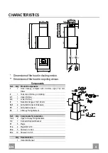
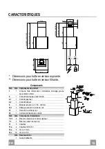
Page 5: ...opy complete with Controls Light Fan unit Filters 2 1 Telescopic chimney comprising 2 1 1 Upper chimney 2 2 1 Lower chimney 9 1 Reduction flange 150 120 mm 14 1 2 Air Outlet Connector Extension 15 1 A...

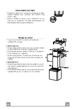
Page 6: ...vided aligning its centre grooves with the vertical reference line Mark the centres of the holes in the bracket Mark a reference point as indicated at 105 mm from the horizontal reference line Drill t...

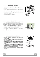
Page 7: ...a 120 mm air exhaust connection insert the reducer flange 9 on the hood body outlet Fix the pipe in position using sufficient pipe clamps not supplied Remove possible charcoal filters 150 9 120 RECIR...

Page 8: ...pen the two side pieces out slightly hook them up behind the brackets 7 2 1 and bring them back together again until they are in contact Fix to the Brackets at the sides using 4 screws 12c 2 9 x 9 5 p...

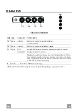
Page 9: ...Fixed When pressed briefly turns the Motor on at Speed three Flashing Pressed for 2 Seconds Activates Speed four with a timer set to 10 minutes after which it returns to the speed that was set previou...

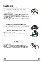
Page 10: ...the handle is visible on the outside Activated charcoal filter Recirculation version These filters are not washable and cannot be regenerated and must be replaced approximately every 4 months of oper...

Page 11: ...nantl vacuationd airdoivent treremplies UTILISATION Lahottea t con ueexclusivementpourl usagedomestique danslebutd liminerlesodeursdelacuisine Nejamaisutiliserabusivementlahotte Nepaslaisserlesflammes...

Page 12: ...clairage groupe de ventilation filtres 2 1 Conduit t lescopique constitu de 2 1 1 Conduit sup rieur 2 2 1 Conduit inf rieur 9 1 Bride de r duction 150 120 mm 14 1 2 Rallonge raccord de sortie de l air...

Page 13: ...centre de l trier entailles sur la ligne verticale de r f rence Marquer les centres des trous de l trier Marquer comme indiqu un point de r f rence 105 mm de la ligne horizontale de rep re Percer les...

Page 14: ...hement avec un tube de 120 mm ins rer le flasque de r duction 9 sur la sortie du corps de la hotte Fixer le tube par des colliers appropri s Le mat riau n cessaire n est pas fourni Retirer les ventuel...

Page 15: ...oque Conduit sup rieur carter l g rement les deux c t s les accrocher derri re les triers 7 2 1 et les refermer compl tement Fixer lat ralement aux triers l aide des 4 vis 12c 2 9 x 9 5 fournies avec...

Page 16: ...ri vement d marre le moteur en troisi me vitesse Clignotant Appuy e pendant 2 secondes D marre la quatri me vitesse avec une temporisation de 10 mi nutes apr s lesquelles le moteur retourne la vitesse...

Page 17: ...visible externe Filtre anti odeur Version filtrante Il ne sont pas lavables ni r g n rables il faut les remplacer au moins tous les 4 mois d emploi ou plus fr quemment en cas d emploi particuli remen...

Page 18: ...ausschlie lichzumEinsatzimprivatenHaushaltundzurBeseitigungvonK chen ger chenvorgesehen Unsachgem erEinsatzderHaubeistzuunterlassen Gro eFlammenbeieingeschalteterHaubeniemalsunbedecktlassen DieIntensi...

Page 19: ...edienelemente Beleuchtung Ventilatorgruppe Filter 2 1 Teleskopkamin bestehend aus 2 1 1 Oberer Kaminteil 2 2 1 Unterer Kaminteil 9 1 Reduzierflansch 150 120 mm 14 1 2 Anschlussverl ngerung Luftauslass...

Page 20: ...r vertikalen Referenz linie gefluchtet wird Die Mitte der L cher des B gels markieren Wie beschrieben einen Bezugspunkt 105 mm von der horizontalen Bezugslinie Die gekennzeichneten Punkte mit einem Bo...

Page 21: ...g angeschlossen werden Bei Verwendung eines Anschlussrohres 120 den Redu zierflansch 9 am Haubenaustritt anbringen Das Rohr mit geeigneten Rohrschellen fixieren Das hierzu erforderliche Material wird...

Page 22: ...stschrauben Oberer Kaminteil Die beiden seitlichen Bleche leicht aufweiten hinter den B geln 7 2 1 einh ngen und bis zum Anschlag verschlie en Seitlich der B gel mit den 4 mitgelieferten Schrauben 12c...

Page 23: ...T3 Betriebsgeschwindigkeit Bleibend Schaltet den Motor bei der dritten Betriebsgeschwindigkeit ein Blinkend Bei 2 Sekunden langem Dr cken Aktiviert die auf 10 Minuten geregelte vierte Betriebsgeschwi...

Page 24: ...Geruchsfilter Umluftversion Sie k nnen weder gewaschen noch wiederverwendet werden und sind alle 4 Betriebsmonate bzw bei starkem Einsatz auch h ufi ger auszutauschen AUSTAUSCHEN DER AKTIVKOHLE FILTE...

Page 25: ...sencuenta Esnecesariorespe tartodaslasnormativasrelativasalconductodedescargadelaire USO Lacampanahasidoconcebidaexclusivamenteparaunusodom stico paraeliminarlosoloresdela cocina Noutilizarlademanerai...

Page 26: ...ana con Mandos Iluminaci n Grupo Ventilador Filtros 2 1 Chimenea telesc pica formada por 2 1 1 Chimenea Superior 2 2 1 Chimenea Inferior 9 1 Arandela de reducci n 150 120 14 1 2 Air Outlet Connection...

Page 27: ...scas en la l nea vertical de refe rencia Marcar los centros de los orificios de la brida Marcar como se indica un punto de referencia a 105 mm de la l nea horizontal de referen cia Perforar con 8 mm l...

Page 28: ...n con el tubo de 120 mm introducir la brida de reducci n 9 en la salida del cuerpo de la campana Fijar el tubo con abrazaderas adecuadas Este material no se proporciona en dotaci n Quitar los filtros...

Page 29: ...menea superior Separar ligeramente las dos faldas laterales engancharlas de tr s de las bridas 7 2 1 y volverlas a cerrar hasta al tope Fijar lateralmente a las bridas con 4 tornillos 12c 2 9 x 9 5 en...

Page 30: ...Presionada brevemente enciende el motor a la tercera velocidad Intermitente Presionada por 2 segundos Activa la cuarta velocidad temporizada a 10 minutos al final de los cuales vuelve a la velocidad...

Page 31: ...parte visible exterior Filtros antiolor Versi n filtrante No se pueden lavar ni regenerar se deben cambiar cada 4 meses o m s a menudo si su uso es muy intenso SUSTITUCI N DE LOS FILTROS DE CARB N AC...

Page 32: ...GR 3 32 650 mm I 120mm 0 04 mBar 2...

Page 33: ...26 81 41 5 300 260 62 5 340 MIN 460 MAX 660 MIN 340 MAX 660 400 MIN 875 MAX 1075 MIN 755 MAX 1075 6 6 1 1 2 1 2 1 1 2 2 1 9 1 150 120 14 1 2 15 1 19 1 7 2 1 2 7 3 1 11 5 11a 2 SB 12 10 12a 5 4 2 x 44...

Page 34: ...GR 3 34 373 105 150 150 12a 650 mm min 7 2 1 1 2 mm 7 2 1 X mm X 105 mm 8 mm 11 12a 4 2 x 44 4 7 3 373 mm 150 mm 12 mm 11a...

Page 35: ...GR 3 35 Vr 11a 11a Vr 12a o150 120 mm o120 mm 9 150 9 120 14 1 15 15 7 3 14 1 15 150 mm 15 150 14 1 7 3...

Page 36: ...GR 3 36 3 mm 4 12c 19 7 2 1 4 12c 2 9 x 9 5 19 2 12c 2 9 x 9 5...

Page 37: ...GR 3 37 T2 T1 L T3 LED T1 T2 T3 2 10 L T1...

Page 38: ...GR 3 38 2 4 A B A B 20 W...

Page 39: ...RU 3 39 650 I 120 0 04 2...

Page 40: ...126 81 41 5 300 260 62 5 340 MIN 460 MAX 660 MIN 340 MAX 660 400 MIN 875 MAX 1075 MIN 755 MAX 1075 6 6 1 1 2 1 2 1 1 2 2 1 9 1 150 120 14 1 2 15 1 19 1 7 2 1 2 7 3 1 11 5 11a 2 SB 12 10 12a 5 4 2 44...

Page 41: ...RU 4 41 373 105 150 150 12a 650 7 2 1 1 2 7 2 1 X X 105 8 11 12a 4 2 x 44 4 7 3 373 150 12 11a...

Page 42: ...RU 4 42 Vr 11a 2 11a Vr 12 150 120 120 9 150 9 120 14 1 15 15 7 3 14 1 15 150 15 150 14 1 7 3...

Page 43: ...RU 4 43 3 4 12c 19 7 2 1 4 12 2 9 x 9 5 19 2 12 2 9 x 9 5...

Page 44: ...RU 4 44 T2 T1 L T3 T1 T2 T3 2 10 L T1...

Page 45: ...RU 4 45 2 4 A B 20...

Page 46: ...SA 4 46 650 a 120 0 04 2...

Page 47: ...5 300 260 62 5 340 MIN 460 MAX 660 MIN 340 MAX 660 400 MIN 875 MAX 1075 MIN 755 MAX 1075 6 6 1 1 2 1 2 1 1 2 2 1 7 1 8 1 9 1 150 120 10 1 150 14 1 2 15 1 19 1 7 2 1 2 7 3 1 11 4 11a 2 SB 12 10 12a 4...

Page 48: ...SA 4 48 373 105 150 150 12a 650 7 2 1 1 2 7 2 1 X X 105 8 11 12a 4 2 x 44 4 7 3 373 150 12 11a...

Page 49: ...SA 4 49 2 Vr 11a 11a Vr 12a 120 150 120 9 150 9 120 14 1 15 15 7 3 14 1 15 120 150 15 150 14 1 7 3...

Page 50: ...SA 5 50 19 4 12c 7 2 1 4 12 c 2 9 x 9 5 19 2 12 c 2 9 x 9 5...

Page 51: ...SA 5 51 T2 T1 L T3 T1 T2 T3 2 10 L T1...

Page 52: ...SA 5 52 4 A B A B 20...

Page 53: ......

Page 54: ......

Page 55: ......

Page 56: ...436005912_ver2...

Reviews: