background image


EN 

8


ELECTRICAL CONNECTION 

•  Connect the hood to the mains through a two-pole switch 

having a contact gap of at least 3 mm. 

•  Remove the grease filters (see paragraph Maintenance) be-

ing sure that the connector of the feeding cable is correctly 
inserted in the socket placed on the side of the fan. 


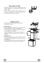
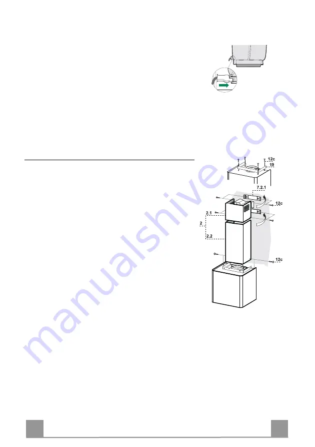
Chimney Assembly 

•  Fasten the Chimney fixing element 

19

 to the Body using 4 

screws 

12c

.


Upper chimney 

•  Open the two side pieces out slightly, hook them up behind 

the brackets 

7.2.1

 and bring them back together again until 

they are in contact.  

•  Fix to the Brackets at the sides, using 4 screws 

12c

 (2.9 x 

9.5) provided. 

•  If there are any, make sure that the Connector extensions 

outlet is in correspondence with the Chimney openings. 

Lower chimney  

•  Open the two side pieces of the Chimney out slightly, hook 

them between the upper chimney and the wall, and then 
close them together again until they are in contact.  

•  Fix the part at the sides to the Chimney fixing element 

19

using 2 screws 

12c 

(2.9 x 9.5) provided. 


Summary of Contents for Lithos EG6 BK A45

Page 1: ...Instructions Manual Manuel d Instructions Bedienungsanleitung Manual de instrucciones...

Page 2: ...SUGGESTIONS 11 CARACTERISTIQUES 12 INSTALLATION 13 UTILISATION 16 ENTRETIEN 17 INHALTSVERZEICHNIS EMPFEHLUNGEN UND HINWEISE 18 CHARAKTERISTIKEN 19 MONTAGE 20 BEDIENUNG 23 WARTUNG 24 NDICE CONSEJOS Y S...

Page 3: ...EN 3 3 46 47 48 51 52 SA...

Page 4: ...lationforthegashobspecifyagreaterdistancespecifiedabove thishas tobetakenintoaccount Regulationsconcerningthedischargeofairhavetobefulfilled USE Theextractorhoodhasbeendesignedexclusivelyfordomesticus...

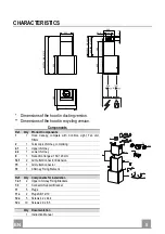
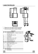
Page 5: ...opy complete with Controls Light Fan unit Filters 2 1 Telescopic chimney comprising 2 1 1 Upper chimney 2 2 1 Lower chimney 9 1 Reduction flange 150 120 mm 14 1 2 Air Outlet Connector Extension 15 1 A...

Page 6: ...vided aligning its centre grooves with the vertical reference line Mark the centres of the holes in the bracket Mark a reference point as indicated at 105 mm from the horizontal reference line Drill t...

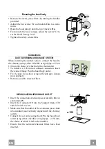
Page 7: ...a 120 mm air exhaust connection insert the reducer flange 9 on the hood body outlet Fix the pipe in position using sufficient pipe clamps not supplied Remove possible charcoal filters 150 9 120 RECIR...

Page 8: ...pen the two side pieces out slightly hook them up behind the brackets 7 2 1 and bring them back together again until they are in contact Fix to the Brackets at the sides using 4 screws 12c 2 9 x 9 5 p...

Page 9: ...Fixed When pressed briefly turns the Motor on at Speed three Flashing Pressed for 2 Seconds Activates Speed four with a timer set to 10 minutes after which it returns to the speed that was set previou...

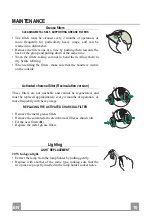
Page 10: ...the handle is visible on the outside Activated charcoal filter Recirculation version These filters are not washable and cannot be regenerated and must be replaced approximately every 4 months of oper...

Page 11: ...nantl vacuationd airdoivent treremplies UTILISATION Lahottea t con ueexclusivementpourl usagedomestique danslebutd liminerlesodeursdelacuisine Nejamaisutiliserabusivementlahotte Nepaslaisserlesflammes...

Page 12: ...clairage groupe de ventilation filtres 2 1 Conduit t lescopique constitu de 2 1 1 Conduit sup rieur 2 2 1 Conduit inf rieur 9 1 Bride de r duction 150 120 mm 14 1 2 Rallonge raccord de sortie de l air...

Page 13: ...centre de l trier entailles sur la ligne verticale de r f rence Marquer les centres des trous de l trier Marquer comme indiqu un point de r f rence 105 mm de la ligne horizontale de rep re Percer les...

Page 14: ...hement avec un tube de 120 mm ins rer le flasque de r duction 9 sur la sortie du corps de la hotte Fixer le tube par des colliers appropri s Le mat riau n cessaire n est pas fourni Retirer les ventuel...

Page 15: ...oque Conduit sup rieur carter l g rement les deux c t s les accrocher derri re les triers 7 2 1 et les refermer compl tement Fixer lat ralement aux triers l aide des 4 vis 12c 2 9 x 9 5 fournies avec...

Page 16: ...ri vement d marre le moteur en troisi me vitesse Clignotant Appuy e pendant 2 secondes D marre la quatri me vitesse avec une temporisation de 10 mi nutes apr s lesquelles le moteur retourne la vitesse...

Page 17: ...visible externe Filtre anti odeur Version filtrante Il ne sont pas lavables ni r g n rables il faut les remplacer au moins tous les 4 mois d emploi ou plus fr quemment en cas d emploi particuli remen...

Page 18: ...ausschlie lichzumEinsatzimprivatenHaushaltundzurBeseitigungvonK chen ger chenvorgesehen Unsachgem erEinsatzderHaubeistzuunterlassen Gro eFlammenbeieingeschalteterHaubeniemalsunbedecktlassen DieIntensi...

Page 19: ...edienelemente Beleuchtung Ventilatorgruppe Filter 2 1 Teleskopkamin bestehend aus 2 1 1 Oberer Kaminteil 2 2 1 Unterer Kaminteil 9 1 Reduzierflansch 150 120 mm 14 1 2 Anschlussverl ngerung Luftauslass...

Page 20: ...r vertikalen Referenz linie gefluchtet wird Die Mitte der L cher des B gels markieren Wie beschrieben einen Bezugspunkt 105 mm von der horizontalen Bezugslinie Die gekennzeichneten Punkte mit einem Bo...

Page 21: ...g angeschlossen werden Bei Verwendung eines Anschlussrohres 120 den Redu zierflansch 9 am Haubenaustritt anbringen Das Rohr mit geeigneten Rohrschellen fixieren Das hierzu erforderliche Material wird...

Page 22: ...stschrauben Oberer Kaminteil Die beiden seitlichen Bleche leicht aufweiten hinter den B geln 7 2 1 einh ngen und bis zum Anschlag verschlie en Seitlich der B gel mit den 4 mitgelieferten Schrauben 12c...

Page 23: ...T3 Betriebsgeschwindigkeit Bleibend Schaltet den Motor bei der dritten Betriebsgeschwindigkeit ein Blinkend Bei 2 Sekunden langem Dr cken Aktiviert die auf 10 Minuten geregelte vierte Betriebsgeschwi...

Page 24: ...Geruchsfilter Umluftversion Sie k nnen weder gewaschen noch wiederverwendet werden und sind alle 4 Betriebsmonate bzw bei starkem Einsatz auch h ufi ger auszutauschen AUSTAUSCHEN DER AKTIVKOHLE FILTE...

Page 25: ...sencuenta Esnecesariorespe tartodaslasnormativasrelativasalconductodedescargadelaire USO Lacampanahasidoconcebidaexclusivamenteparaunusodom stico paraeliminarlosoloresdela cocina Noutilizarlademanerai...

Page 26: ...ana con Mandos Iluminaci n Grupo Ventilador Filtros 2 1 Chimenea telesc pica formada por 2 1 1 Chimenea Superior 2 2 1 Chimenea Inferior 9 1 Arandela de reducci n 150 120 14 1 2 Air Outlet Connection...

Page 27: ...scas en la l nea vertical de refe rencia Marcar los centros de los orificios de la brida Marcar como se indica un punto de referencia a 105 mm de la l nea horizontal de referen cia Perforar con 8 mm l...

Page 28: ...n con el tubo de 120 mm introducir la brida de reducci n 9 en la salida del cuerpo de la campana Fijar el tubo con abrazaderas adecuadas Este material no se proporciona en dotaci n Quitar los filtros...

Page 29: ...menea superior Separar ligeramente las dos faldas laterales engancharlas de tr s de las bridas 7 2 1 y volverlas a cerrar hasta al tope Fijar lateralmente a las bridas con 4 tornillos 12c 2 9 x 9 5 en...

Page 30: ...Presionada brevemente enciende el motor a la tercera velocidad Intermitente Presionada por 2 segundos Activa la cuarta velocidad temporizada a 10 minutos al final de los cuales vuelve a la velocidad...

Page 31: ...parte visible exterior Filtros antiolor Versi n filtrante No se pueden lavar ni regenerar se deben cambiar cada 4 meses o m s a menudo si su uso es muy intenso SUSTITUCI N DE LOS FILTROS DE CARB N AC...

Page 32: ...GR 3 32 650 mm I 120mm 0 04 mBar 2...

Page 33: ...26 81 41 5 300 260 62 5 340 MIN 460 MAX 660 MIN 340 MAX 660 400 MIN 875 MAX 1075 MIN 755 MAX 1075 6 6 1 1 2 1 2 1 1 2 2 1 9 1 150 120 14 1 2 15 1 19 1 7 2 1 2 7 3 1 11 5 11a 2 SB 12 10 12a 5 4 2 x 44...

Page 34: ...GR 3 34 373 105 150 150 12a 650 mm min 7 2 1 1 2 mm 7 2 1 X mm X 105 mm 8 mm 11 12a 4 2 x 44 4 7 3 373 mm 150 mm 12 mm 11a...

Page 35: ...GR 3 35 Vr 11a 11a Vr 12a o150 120 mm o120 mm 9 150 9 120 14 1 15 15 7 3 14 1 15 150 mm 15 150 14 1 7 3...

Page 36: ...GR 3 36 3 mm 4 12c 19 7 2 1 4 12c 2 9 x 9 5 19 2 12c 2 9 x 9 5...

Page 37: ...GR 3 37 T2 T1 L T3 LED T1 T2 T3 2 10 L T1...

Page 38: ...GR 3 38 2 4 A B A B 20 W...

Page 39: ...RU 3 39 650 I 120 0 04 2...

Page 40: ...126 81 41 5 300 260 62 5 340 MIN 460 MAX 660 MIN 340 MAX 660 400 MIN 875 MAX 1075 MIN 755 MAX 1075 6 6 1 1 2 1 2 1 1 2 2 1 9 1 150 120 14 1 2 15 1 19 1 7 2 1 2 7 3 1 11 5 11a 2 SB 12 10 12a 5 4 2 44...

Page 41: ...RU 4 41 373 105 150 150 12a 650 7 2 1 1 2 7 2 1 X X 105 8 11 12a 4 2 x 44 4 7 3 373 150 12 11a...

Page 42: ...RU 4 42 Vr 11a 2 11a Vr 12 150 120 120 9 150 9 120 14 1 15 15 7 3 14 1 15 150 15 150 14 1 7 3...

Page 43: ...RU 4 43 3 4 12c 19 7 2 1 4 12 2 9 x 9 5 19 2 12 2 9 x 9 5...

Page 44: ...RU 4 44 T2 T1 L T3 T1 T2 T3 2 10 L T1...

Page 45: ...RU 4 45 2 4 A B 20...

Page 46: ...SA 4 46 650 a 120 0 04 2...

Page 47: ...5 300 260 62 5 340 MIN 460 MAX 660 MIN 340 MAX 660 400 MIN 875 MAX 1075 MIN 755 MAX 1075 6 6 1 1 2 1 2 1 1 2 2 1 7 1 8 1 9 1 150 120 10 1 150 14 1 2 15 1 19 1 7 2 1 2 7 3 1 11 4 11a 2 SB 12 10 12a 4...

Page 48: ...SA 4 48 373 105 150 150 12a 650 7 2 1 1 2 7 2 1 X X 105 8 11 12a 4 2 x 44 4 7 3 373 150 12 11a...

Page 49: ...SA 4 49 2 Vr 11a 11a Vr 12a 120 150 120 9 150 9 120 14 1 15 15 7 3 14 1 15 120 150 15 150 14 1 7 3...

Page 50: ...SA 5 50 19 4 12c 7 2 1 4 12 c 2 9 x 9 5 19 2 12 c 2 9 x 9 5...

Page 51: ...SA 5 51 T2 T1 L T3 T1 T2 T3 2 10 L T1...

Page 52: ...SA 5 52 4 A B A B 20...

Page 53: ......

Page 54: ......

Page 55: ......

Page 56: ...436005912_ver2...

Reviews: