background image

3

ALL  WALL  AND  FLOOR  OPENINGS  WHERE  THE  RANGEHOOD  IS  INSTALLED  MUST  

BE  SEALED.

This rangehood requires at least 24" of clearance 

between the bottom of the rangehood and the 

cooking surface or countertop. This hood has been approved by UL at this distance from the cooktop. 

This minimum clearance may be higher depending on local building codes. For gas cooktops and 

combination ranges, a minimum of 30" is recommended and may be required.

The maximum depth of overhead cabinets is 13". Overhead cabinets on both sides of this unit must be 

a minimum of 18" above the cooking surface or countertop. Consult the cooktop or range installation 

instructions given by the manufacturer before making any cutouts. 

MOBILE HOME INSTALLATION The installation of this rangehood must conform to the Manufactured 

Home Construction and Safety Standards, Title 24 CFR, Part 3280 (formerly Federal Standard for 

Mobile Home Construction and Safety, Title 24, HUD, Part 280). See Electrical Requirements.

• Venting system MUST terminate outside the home.

• 

DO NOT

 terminate the ductwork in an attic or other enclosed space.

• 

DO NOT

 use 4" laundry-type wall caps.

• Flexible-type ductwork is not recommended.

• 

DO NOT

 obstruct the flow of combustion and ventilation air.

• Failure to follow venting requirements may result in a  fire.

   WARNING

!

Cold Weather installations

An additional back draft damper should be installed to minimize backward cold air flow and a nonmetal

-

lic thermal break should be installed to minimize conduction of outside temperatures as part of the vent 

system. The damper should be on the cold air side of the thermal break. The break should be as close 

as possible to where the vent system enters the heated portion of the house.

VENTING   REQUIREMENTS

Determine which venting method is best for your application.  Ductwork can extend either through the 

wall or the roof.

The length of the ductwork and the number of elbows should be kept to a minimum to provide efficient 

performance.  The size of the ductwork should be uniform.  Do not install two elbows together.  Use duct 

tape to seal all joints in the ductwork system.  Use caulking to seal exterior wall or floor opening around 

the cap.

Flexible ductwork is not recommended.  Flexible ductwork creates back pressure and air turbu-

lence that greatly reduces performance.

Make sure there is proper clearance within the wall or floor for exhaust duct before making cutouts.  Do 

not cut a joist or stud unless absolutely necessary.  If a joist or stud must be cut, then a supporting frame 

must be constructed. 

WARNING - To Reduce The Risk Of Fire, Use Only Metal Ductwork.

CAUTION - To reduce risk of fire and to properly exhaust air, be sure to duct air outside – Do 

not vent exhaust air into spaces within walls or ceilings or into attics, crawl spaces, or garages. 

3.  When cutting or drilling into wall or ceiling, do not damage electrical wiring and 

other hidden utilities.

4.  Ducted fans must always be vented to the outdoors.

Summary of Contents for NOPR30SS600

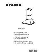
Page 1: ...NOPR30SS600 NOPR36SS600 Installation Instructions Use and Care Information Instructions d installation Utilisez et d entretien Instrucciones de instalaci n Informaci n de uso y cuidado Nova PRO...

Page 2: ...with your back to an exit Based on Kitchen Firesafety Tips published by NFPA WARNING TO REDUCE THE RISK OF FIRE OR ELECTRIC SHOCK do not use this fan with any solid state speed control device WARNING...

Page 3: ...uldbeinstalledtominimizebackwardcoldairflowandanonmetal lic thermal break should be installed to minimize conduction of outside temperatures as part of the vent system The damper should be on the cold...

Page 4: ...or grounding DO NOT ground to a gas pipe DO NOT have a fuse in the neutral or grounding circuit A fuse in the neutral or grounding circuit could result in electrical shock Check with a qualified elect...

Page 5: ...5 RANGEHOOD DIMENSIONS Min 24 Min 30...

Page 6: ...2e 3 Screws 1 8 x 1 4 Qty Documentation 1 Instruction Manual Available Accessories Direct Connect Wiring Box sku number WIREBOX Activated Charcoal Filter sku FILTER1LL High Ceiling Chimney Kit Upper a...

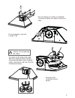
Page 7: ...equires purchase of Activated Charcoal Accessory Horizontal Vertical 6 I Install Damper that is included with the Hood before connecting to the ductwork Only for Ducted Venting Installation Remove the...

Page 8: ...8 6 Rear Ducted Venting Options Installation Ducting Methods The Electrical Connector must be removed first before converting the hood to Rear Ducting mode Rear Ducted Venting diagram...

Page 9: ...using light force on one tab with a flat head screwdriver Remove the 2 screws as shown in the image to the left from the top electrical cover and set aside As shown in the image to the left pull out t...

Page 10: ...allation the motor needs to be unsecured by first removing the 12 screws as shown Once the screws are removed extract the blower from the body of the Hood and position it so the transition opening is...

Page 11: ...ood body Reconnect the Connectors to the blower Fix the Supplied Cover with 3 screws 12e As shown in the image to the right take the cable and cover removed previously and place back in original posit...

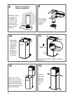
Page 12: ...al reference lineandmarkthewallatthecentersoftheholesinthebracket Place the other bracket 7 2 1 on the wall as shown below the first bracket at the height of the upper chimney section supplied and ali...

Page 13: ...re marked insert 2 wall plugs 11 in the holes and fix with 2 screws 5 16 Fix the brackets 7 1 using the 12a screws supplied in the hood body fixing holes as shown Screw the two screws 12d supplied ont...

Page 14: ...1 using the screws 12a supplied 12 Slightly widen the two sides of the lower section and hook them between the upper section and the wall making sure that they are properly housed Install Roof or Wal...

Page 15: ...rackets and connect to the Ductless Diverter mak ing sure that they are well seated 15 12a Fix the lower Bracket 7 2 1 with two screws 12a supplied as shown N 4x 12b Secure the sides to the brackets b...

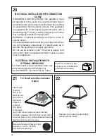
Page 16: ...groundinginstructions are not completely understood or if doubt exists as to whether the appliance is properly grounded Do not use an extension cord If the power supply cord is too short have a qualif...

Page 17: ...ctivate the INTENSIVE SPEED which is timed to run for 10 minutes At the end of this time it will automatically return to the speed set before Suitable to deal with maximum levels of cooking fumes If y...

Page 18: ...e safety knobs provided pull and turn Replacing Activated Charcoal Filter The Activated Charcoal Filters are not washable and cannot be regenerated and should be replaced approximately every 4 months...

Page 19: ...19 Wiring Diagram...

Page 20: ...om accident alteration misuse abuse fire flood acts of God improper installation installation not in accordance with electrical or plumbing codes or Faber documentation or use of products not approved...

Reviews: