background image

Version 04/08 - Page 6

PREPARE  THE  CABINET

1. 

Disconnect and move freestanding range from cabinet 

opening to provide easier access to upper cabinet and rear 

wall.  Put a thick, protective covering over cooktops, set-in 

ranges or countertops to protect from damage or dirt.

2. 

Determine and clearly mark with a pencil the center line 

of the cabinet on the wall and on the underside of the cabinet 

where the rangehood will be installed.

3. 

Determine the proper cutouts for the ductwork.  Make 

all necessary cuts in the walls or cabinets for the ductwork.  

Install the ductwork before mounting the rangehood.

4. 

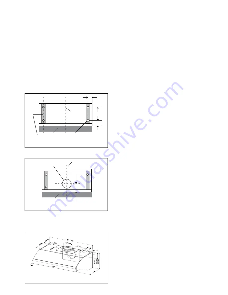
If the cabinet bottom is recessed, wood filler strips need 

to be installed.

5. 

Drill  four  3/16"  clearance  holes  for  hood  mounting 

screws.

FIGURE 6

7. 

Determine and make the proper cutout for the Power 

Supply Cable.  Use a 1  1/4" Drill Bit to make this hole.  Run 

the Power Supply Cable through the wall or cabinet.  DO NOT 

turn on the power until installation is complete.  Use caulking 

to seal around the wire opening.

FIGURE 7

FIGURE 8

8. 

Remove the grease filters.

9. 

Remove the terminal box cover (located on the back 

wall of the hood.  Remove the power supply cable knockout 

using a flat-blade screwdriver.  Attach strain relief in power 

supply cable opening so that clamping screws are inside of 

rangehood.

10. 

Attach damper to exhaust opening on top of the range

-

hood using the two small screws from the hardware pack

-

age.

INSTALL  THE  RANGEHOOD

1. 

Place the rangehood mounting screws close to the holes 

in the cabinet bottom.

2. 

Lift rangehood into place while feeding wiring through 

strain relief.

3. 

Insert the screws through the clearance holes and start 

them into the rangehood.

4. 

Connect the vent system to the rangehood and seal all 

joints with duct tape.

5. 

Connect the Power Supply Cable to the rangehood.  

Attach the White lead of the power supply to the White lead 

of the rangehood with a twist-on type wire connector.  Attach 

the Black lead of the power supply to the Black lead of the 

rangehood with a twist-on type wire connector.  Connect the 

Green ( Green and Yellow ) ground wire under the Green 

grounding screw.

6. 

Replace the grease filters.

7. 

Turn the power supply on.  Turn on blower and lights.  If 

the rangehood does not operate, check that the circuit breaker 

is not tripped or the house fuse blown.  If the unit still does 

not operate, disconnect the power supply and check that the 

wiring connections have been made properly.

6

.  Cut  a  6  1/2"  diameter  hole  in  cabinet  bottom  as 

shown.

CENTERLINE

WALL

v

v

DIAMETERHOLE

CENTERLINE

WALL

WOODlLLERSTRIPS

RECESSEDCABINET

BOTTOMSONLY 

v

CLEARANCE

HOLES

v

v

v

Summary of Contents for PELLICANO

Page 1: ...Title 24 HUD Part 280 Four wire power supply must be used and the appliance wiring must be revised See Electrical Requirements LISEZ BIEN CETTE FICHE AVANT D INSTALLER LA HOTTE AVERTISSEMENT POURMINI...

Page 2: ...nction box When making the electrical connection cut a 1 1 4 hole in the wall A hole cut through wood must be sanded until smooth A hole through metal must have a grommet WARNING TO REDUCE THE RISK OF...

Page 3: ...pareils combustion Suivez les conseils et mesuresdes curit dufournisseurtelsqueceuxpubli s par l Association Nationale de la Sauvegarde contre l Incendie et l Association Am ricaine d Ing nieurs de Ch...

Page 4: ...terature Package PARTS NEEDED FOR INSTALLATION 2 Conduit Connectors Power Supply Cable 1 Wall or Roof Cap All Metal Ductwork OPTIONAL ACCESSORIES AVAILABLE Charcoal Filter Kit For recirculating instal...

Page 5: ...e exhaust plate and flip motor to the rear exit The Pellicano requires 6 round ductwork To en surethattheblowerperformstoitshighestpossible capacity ductwork should be as short and straight as possilb...

Page 6: ...ver Attach strain relief in power supply cable opening so that clamping screws are inside of rangehood 10 Attach damper to exhaust opening on top of the range hood using the two small screws from the...

Page 7: ...the Halogen Lamps Before you begin make sure that the rangehood is turned off and that the other lamps have had sufficient time to cool Halogen bulbs burn extremely hot and serious injury could result...

Page 8: ...umbing 2 Service calls to repair or replace range hood light bulbs fuses or filters Those consumable parts are excluded from warranty coverage 3 Repairs when your range hood is used for other than nor...

Page 9: ...de documentation PI CES N CESSAIRES POUR L INSTALLATION 2 connecteurs de conduit C ble d alimentation 1 capuchon de mur ou de toit Conduit en m tal ACCESSOIRES POUR L INSTALLATION Filtres au Charbon P...

Page 10: ...CALCUL DE LONGUEUR DU CONDUIT 3 0 pi 5 0 pi 12 0 pi 0 0 pi Coude 45 Coude 90 Coude plat 90 Capuchon de mur FIGURE 4 9 pi de conduit droit 2 Coudes 90 Capuchon de mur Syst me total 9 0 pi 10 0 pi 0 0 p...

Page 11: ...rre c ble sur le trou veiller ce qu il soit facile de visser les vis de bridage l int rieur de la hotte 10 Installer le clapet anti reflux sur l ouverture de sortie au sommet de la hotte utiliser deux...

Page 12: ...ques minutes apr s la cuisson pour liminer la fum e et les odeurs de la cuisine Nettoyage Les filtres graisse en m tal devraient tre nettoy s fr quemment dans une solution d eau chaude et de d tergent...

Page 13: ...r les fusibles de votre maison ou pour corriger votre c blage ou votre syst me de plomberie 2 Les appels de service pour remplacer ou r parer les ampoules les fusibles ou les filtres de votre hotte de...

Page 14: ......

Reviews: