background image

Version 3/15 - Page 5

9 Feet Straight Duct

2 - 90˚ Elbows

Wall Cap

Total System

9.0 feet

14.0 feet

0.0 feet

23.0 feet

FIGURE  2

5.0 feet

7.0 feet

12.0 feet

0.0 feet

45˚ Elbow

90˚ Elbow

90˚ Flat Elbow

Wall Cap

FIGURE  1

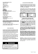
TOOLS NEEDED FOR INSTALLATION

• Saber Saw or Jig Saw

• Drill

• 1  1/4" Wood Drill Bit

• Pliers

• Phillips Screwdriver

• Flat Blade Screwdriver

• Wire Stripper or Utility Knife

• Metal Snips

• Measuring Tape or Ruler

• Level

• Pencil

• Caulking Gun

• Duct Tape

• 7 MM Nut Driver
PARTS SUPPLIED FOR INSTALLATION

• 6 Mounting Brackets (2 support legs, 2 under counter and

   2 over-counter brackets

• 2 End Caps

• 2 Stainless Grease Filters

• Stainless steel top strip

• Nuts to connect top strip

• Installation Screws

• 1 Literature Package

PARTS NEEDED FOR INSTALLATION

• 2 Conduit Connectors

• Power Supply Cable

• Wiring Cable - Optional Remote Blower Only

• 1 Wall or Roof Cap

• All Metal Ductwork

CHOOSE A BLOWER TO PAIR WITH THE SCIROCCO PLUS

• Internal Blower model #IBDD600

-B

• Remote Blower model # RB900 OR RB1200
• Use your existing remote blower rated at max 2

,8

 Amp suitable for


use with solid state variable speed control

PLAN THE DUCTWORK

The Scirocco Plus downdraft system is designed to offer wide 

flexibility in ducting.  The interior  blower can be ducted on the 

front or back of the downdraft unit in multiple directions: down, 

left, right or backwards (front side only) using a  6" round vent.   

The remote blower can be ducted from the front or back of the 

downdraft unit, pointing down using a 10" round vent.  

The remote  blower requires a separate wiring cable that 

should be installed at the same time that the ductwork is 

installed.  For best results, 10" duct is recommended for the 

remote blower.  A damper plate is included in the box with the 

downdraft package and  must be attached over the 

opening  of  the  front  /  back  of  the  downdraft  blower  box.  

Remote blower can be mounted on either an outside wall or 

the roof of the home.

CALCULATE THE DUCTRUN LENGTH

The ductwork length should not exceed 55 equivalent feet for 

6" duct, or 75 equivalent feet for 10" round duct.   Calculate 

the length of the ductwork by adding the equivalent feet listed 

in FIGURE 1 for each piece of duct in the complete system.  

An example is given in FIGURE 2.

For best results, use no more than three 90°  elbows.  Make 

sure that there is a minimum of 24" of straight duct between 

elbows if more than one is used.  Do not install two elbows 

together.  Round duct is recommended instead of rectangular 

duct especially if elbows are needed.  For internal blower  

models, rectangular duct should be transitioned to 6" round 

as soon as possible.

When planning the cutout for the downdraft:

• Draw  both  the  cooktop  and  downdraft  cutouts  on  the

countertop before making any cuts.

• Check that there is enough room in the cabinet for both.

 Failure to follow these warnings could result in damage to 

the countertop.

   WARNING

!

GENERAL INSTALLATION GUIDELINES 

(IMPORTANT - READ BEFORE INSTALLATION)

The Scirocco Plus is meant to be installed with residential 

use cook tops, cook tops / oven combinations, free standing 

ranges WITHOUT backguards and range tops. This product 

is not recommended for use with slide in ranges which may 

require additional space behind the range for oven venting OR 

with freestanding ranges WITH backguards.  Always consult 

your cooking manufacturer installation instructions for cooking 

product dimensions and specific cfm needs.

In the event of installations where the blower is located 

on the back of the unit, it is advised to leave an access 

door or opening to reach the bottom of the Scirocco 

Plus where the wiring box and motor is located should 

service be needed. 

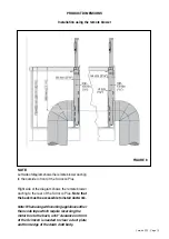
NOTE: When using this hood with a range top or free 

standing range with the motor box reversed behind 

the hood, a 3/4" clearance is required on the front 

of the hood to clear a duct plate and front edge of 

the down draft body. A filler strip may be needed on 

the counter top in this type of installation to cover 

this gap between the cooking surface and the hood.

CAUTION

  -  To  Reduce  The  Risk  Of  Fire  And  Electric 

Shock,  Install  This  Rangehood  Only  With  Remote  Blower 

Models  Rated  Maximum  2,8  suitable  for  solid  state  speed 

control  A Or Remote or Integral Blowers Manufactured by 

Faber listed above.

Summary of Contents for SCIR3014SSNB-B

Page 1: ...SCIR3014SSNB B SCIR3614SSNB B Installation Instructions Use and Care Information Instructions d installation Utilisez et d entretien DOWN DRAFT...

Page 2: ...with your back to an exit Based on Kitchen Firesafety Tips published by NFPA WARNING TO REDUCE THE RISK OF FIRE OR ELECTRIC SHOCK do not use this fan with any solid state speed control device WARNING...

Page 3: ...The length of the ductwork and the number of elbows should be kept to a minimum to provide efficient performance The size of the ductwork should be uniform Do not install two elbows together Use duct...

Page 4: ...ld be connected directly to the fused disconnect or circuit breaker through flexible armored or nonmetallic sheathed copper cable Allow some slack in the cable so the appliance can be moved if servici...

Page 5: ...or 75 equivalent feet for 10 round duct Calculate the length of the ductwork by adding the equivalent feet listed in FIGURE 1 for each piece of duct in the complete system An example is given in FIGUR...

Page 6: ...URE 4 FIGURE 3 Dimensions with IBDD600 B Internal blower box The blower box can be mounted in such a way that the vent collar is aligned to the left the right downwards or towards the rear as desired...

Page 7: ...30 36 FIGURE 5 NOTE A Left right IBDD600 B ducting B Ducting IBDD600 B down C Ducting IBDD600 B to the rear D Power cord cut out for Remote Blower E 10 Ducting for Remote Blower a Cooktop overhang b...

Page 8: ...installing the exhaust ducting to the front appropriate clearances must be maintained in the cabinet INSTALLATION NOTES The specified dimensions minimum cut out dimensions must be observed If an oven...

Page 9: ...cirocco Plus Right Side of the diagram shows the IBDD600 B mounted behind the Scirocco Plus The blower must be accessible to install the ductwork Note When using with cooking applainces other than coo...

Page 10: ...co Plus Right side of the diagram shows the remote blower ducting to the rear of the Scirocco Plus Note that the back must be accessible to install ductwork Note Whenusingwithcookingapplaincesother th...

Page 11: ...must not be installed in an area where there are strong drafts for instance near windows doors etc 2 Remove the 10 round connection plate from the front of the downdraft FIGURE 9 3 Put the top mounti...

Page 12: ...untertop for additional support First loosely screw the brackets into the sliding nuts in the housing and push them up under the countertop Pre drill the mounting holes into the countertop from undern...

Page 13: ...or thru the rear of the cabinet IF USING A REMOTE BLOWER TURN TO REMOTE BLOWER INSTALLATION ON PAGE 15 See FIGURE 14 for venting left right or down Disconnect the cable from inside the hood Plug in th...

Page 14: ...unt the previously removed cover onto the front of the unit FIGURE 25 FIGURE 23 FIGURE 24 FIGURE 25 PREPARE ELECTRICAL CONNECTION Remove the cover of the terminal box FIGURE 26 Decide whether the powe...

Page 15: ...t 6 round ducting to the unit FIGURE 29 REMOTE BLOWER INSTALLATION When using the remote blower a connection plate must be installed on the hood instead of a blower box It can be mounted to the front...

Page 16: ...wndraft vent fuse located under the power board 4 Connect the vent system to 6 IBDD600 B blower or 10 remote blowers round vent collar plate Position the vent to avoid wall studs and floor joists Comp...

Page 17: ...into the knock out Connect the home power into the box as described on the previous page Using FIGURE 34 as a guide connect the remote blower wiring as follows into the downdraft box Blue on the righ...

Page 18: ...ft vent you must turn the downdraft vent off immediately It is possible to cause damage to the downdraft vent if water is allowed inside the downdraft vent while it is operating Please follow these st...

Page 19: ...he filters are not in their proper position If the filters top tabs are not locked behind the top flange the vent may retract but not raise back up If retractable downdraft vent does not operate after...

Page 20: ...K BLU RED ORG GRY WHT BLU BLK GRY RED BLK 7 BLK F BRW BLU BLK RED PNK MOTOR 6 5 N 4 3 BLU 2 L B L B 1 BRW Y G BRW 220 240V 50Hz 220V 60Hz 110 127V 60Hz USA LUX2 2 BLU 1 AUX Faber ATF 2 ORG 1 ORG LUX1...

Page 21: ...om accident alteration misuse abuse fire flood acts of God improper installation installation not in accordance with electrical or plumbing codes or Faber documentation or use of products not approved...

Page 22: ...Une voie de sortie se trouve derri re vous pendant que vous teignez les flammes D apr s le guide Kitchen Firesafety Tips publi par la NFPA aux tats Unis AVERTISSEMENT POURR DUIRELERISQUED INCENDIEOUD...

Page 23: ...lence qui diminuent grandement l efficacit de l appareil Assurez vous que l espace libre dans le mur ou le plancher est suffisant pour le conduit d vacuation avant de pratiquer les ouvertures Ne coupe...

Page 24: ...u sectionneur fusible ou au disjoncteur par un c ble flexible de cuivre avec blindage ou gaine non m tallique Laissez un peu de jeu dans le c ble pour permettre le d placement de l appareil si des tra...

Page 25: ...pourrait entra ner des dommages sur le comptoir AVERTISSEMENT OUTILS REQUIS POUR L INSTALLATION Saber scie sauteuse Perceuse 1 1 4 Foret bois Pinces Tournevis Phillips tournevis lame plate Pince d nu...

Page 26: ...bo te du ventilateur La bo te de ventilateur peut tre mont dans de telle sorte que la collerette d vacuation est align s sur la gauche la droite vers le bas ou vers l arri re comme vous le souhaitez F...

Page 27: ...roite IBDD600 B conduits B Canalisation IBDD600 B bas C Canalisation IBDD600 B l arri re D Cordon d alimentation taill pour la soufflerie t l commande E 10 Conduits pour soufflerie distance un surplom...

Page 28: ...Si vous installez le conduits d chappement l avant les autorisations appropri es doivent tre maintenu dans l armoire REMARQUES SUR L INSTALLATION Le minimum sp cifi les dimensions d coup es dimension...

Page 29: ...u diagramme montre la IBDD600 B mont derri re le plus Scirocco Le ventilateur doit tre accessible installer le r seau de conduits Remarque Lors de l utilisation avec applainces de cuissonautresquetabl...

Page 30: ...t du diagramme montre la soufflerie distance conduits l arri re de la plus Scirocco Notez que l arri re doit tre accessible installer les conduits Remarque Lors de l utilisation avec applainces de cui...

Page 31: ...doit pas tre install dans une zone o il ya des courants forts par exemple pr s des fen tres portes etc 2 Retirez le 10 plaque de raccordement ronde l avant de l courant descendant FIGURE 9 3 Mettre l...

Page 32: ...ire Tout d abord visser sans serrer les supports dans les crous coulissants dans le logement et les pousser sous le comptoir Pr percer les trous de montage dans le comptoir de en dessous Utilisez des...

Page 33: ...sol droite gauche ou travers l arri re de l armoire SI VOUS UTILISEZ UN soufflerie distance se tourner vers VENTILATEUR Installation distance sur PAGE 15 Voir Figure 14 pour l a ration gauche la droi...

Page 34: ...avez termin montez le pr alable capot retir sur l avant de l unit FIGURE 25 FIGURE 23 FIGURE 24 FIGURE 25 PR PARER BRANCHEMENT ELECTRIQUE Retirer le couvercle de la bo te bornes FIGURE 26 D cider si...

Page 35: ...e 35 figure 36 Raccorder 6 Conduit rond l unit FIGURE 29 DISTANCE INSTALLATION DE LA SOUFFLERIE Lorsque vous utilisez la soufflerie distance une plaque de connexion doit tre install sur le capot au li...

Page 36: ...itu e sous la carte de puissance 4 Branchez le syst me de ventilation 6 IB DD600 ventilateur ou 10 soufflerie t l com mande conduit rond collerette Positionner l vent pour viter les montants du mur et...

Page 37: ...s raccords de conduit dans le knock out Branchez l alimentation domicile dans la zone telle que d crite la page pr c dente En utilisant la figure 34 comme un guide connecter le c blage du ventilateur...

Page 38: ...e d extraction vous devez ac tiver le syst me d extraction imm diatement Il est possible de causer des dommages l I appareil si l eau est autoris s l int rieur du syst me d extraction alors qu il est...

Page 39: ...s et le dos pour permettre aux languettes sup rieures enclencher en place REMARQUE I appareil ne fonctionne pas si les filtres ne sont pas dans la bonne position Si les filtres languettes sup rieures...

Page 40: ...LK BLU RED ORG GRY WHT BLU BLK GRY RED BLK 7 BLK F BRW BLU BLK RED PNK MOTOR 6 5 N 4 3 BLU 2 L B L B 1 BRW Y G BRW 220 240V 50Hz 220V 60Hz 110 127V 60Hz USA LUX2 2 BLU 1 AUX Faber ATF 2 ORG 1 ORG LUX1...

Page 41: ...es d coulant d un accident d une modification de l utilisation incorrecte ou abusive d un incendie d une inondation d un cas de force majeure d une installation inad quate d une installation non confo...

Page 42: ......

Page 43: ......

Page 44: ...991 0454 786_03 161116 D003075_02...

Reviews: